5-Layer Design
A typical five layer design consists of
- Rigid Material
- Adhesive
- Flexure MAterial
- Adhesive
- Rigid Material
Preparing your Cut Files
You should have already generated cutfiles using the process outlined in the last chapter.
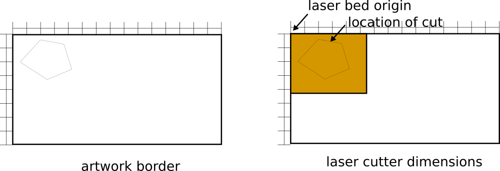
A good idea is to use the same page dimensions in your arwork as the bed of the laser. It is also a good idea to combine cut files for the same material using a dxf or pdf editing tool, in order to minimize the number of manual operations. Just make sure that layer 4 adhesive images are mirror-imaged. More on that below….
Turn off all fill colors. You will not be rastering anything.
Another good idea is to use the color of your vector art to control whether something is used as a placement guide or is actually cut. Often you can set red to be cut, while blue is ignored by the laser-cutter software. This will be used later.
First-pass cut considerations
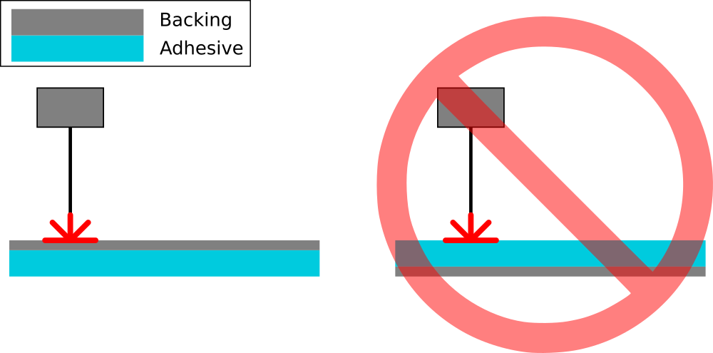
For single-material sheets which are cut out in the laser by themselves, there is freedom in how you rotate and orient your cut pattern when sending it to the laser. It can be a mirror image of itself, and when you remove that material, you can flip it back over to use it. Materials with a backing, however, must be cut so that the orientation of the artwork matches the process of manufacturing.
If you are using a paper-backed adhesive, for example, its backing enforces which layer gets adhered to first, an important manufacturability consideration. For example, if you cut a pattern with the adhesive down and backing up in the laser, the adhesive layer must be bonded to the layer below it in the stack order. If you cut the material with the adhesive up and backing down, it must first be bonded to the layer above it before the backing can be removed. In addition, you must consider ease of cutting as well. For standard paper-backed acrylic adhesive, it is sometimes easier to place it adhesive-side down in the laser, as the tacky adhesive holds itself down and prevents curling. Thus, any adhesive which must be bonded to the material above it in the stack order must have its artwork mirrored if it is to be placed adhesive-facing down in the laser cutter.
Let’s consider this in the context of a five layer laminate, with layer 1 on the bottom of the stack, and layer 5 on the top. This means that the adhesive layer’s artwork (layer 2), if cut out with adhesive facing down in the laser cutter, must be bonded to the top of layer 1 before the backing can be peeled away. This is desireable for the lamination step, as layer 3, the flexible layer, is less controllable as it is more flexible, and bonds to the adhesive even if it lightly touches it, making it more possible to have a manufacturing mistake.
Now think about the adhesive on layer 4. With the adhesive side down in the laser, the resulting cut will have the adhesive side touching layer 3. Due to the above-mentioned manufacturability considerations, it is desirable for this thin, flexible adhesive layer to face the rigid layer instead (layer 5). Thus, layer 4 adhesive artwork should be mirror-imaged, so that the adhesive faces up when placed in the stack, not down.
Second-pass cut considerations
When aligning your second pass cut, it is useful to re-use the rigid-layer cutfile to place the second-pass cut directly over the hole created in the first pass cut. This makes it possible to use the rigid material left in the machine after the last first-pass cut to be reused after you have laminated all the layers together. Utilize colors to bring in your second pass cut and align it to the first pass cut (use snapping or specify the position based on the position of the first-pass cut geometry.), and then disable the first pass cut by setting it to a color the laser will ignore.
Cut first-pass cut for all layers
Preparing your Cut Settings
Disable raster cuts. All cuts computed by our manufacturing code is intended to be cut all-the-way through.
While each laser cutter is different, lets discuss a good strategy for ideally finding the best cut setting for your laser. Start with the laser cutter at 100% speed and 100% power. Perform a small test cut on your material in the top left corner by drawing a small box and checking to see if the box falls out of the material when cut. If the material can be fully cut out, divide the power by half and try the cut again, moving the square to the right by a small amount so you don’t cut over the same spot twice. Continue this process until you have lowered the power to where it consistently cuts through your part, but uses the least amount of power possible.
Conversely, if at 100% speed and 100% power the material is not fully cut out, lower the speed by half until you repeatedly can cut through the material. For example, go from 100% to 50% to 25% to 12%. Once you are able to fully cut through the material, slowly raise the speed as much as you can.
It is a good idea to test your speeds and power out on a small piece of scrap material. Then record your cut settings as you will need these often.
Laser cutters often have different power settings for raster and vector. Since we are only doing vector cuts, you can turn off the raster setting.
Additionally, some laser cutters have path optimization options. Select the “inside-out” strategy if available, as this will guarantee that your material, when cut, is not first separated from the surrounding material which is holding it.
If there is a “centering” option, it is a good idea to disable it if you have already defined a page size equal to the laser bed size. This will enable you to place your artwork exactly where you want it to be cut in the bed. This option can sometimes be found in the laser cut settings as well as the printer preferences settings.
Lenses and Focusing:
Some laser cutters have multiple lens options. For a thick laminate, try using a longer focal length lens. This will make the laser less susceptible to small variations in thickness or height, at the expense of perhaps a smaller spot size – and kerf width.
Additionally, for thick laminates, some times it is appropriate to adjust the bed height across several passes. I have at times adjusted the bed after focusing so that the height is at the laminates top, mid, and bottom planes across 3 or more passes. This ensures that the laser is focused at multiple heights in case your laser is having trouble cutting through a thick laminate. Tighter integration with laser manufacturers might permit this setting to be automated in the future.
This cut should also include any layer identification you will need to identify each layer of your laminate. The rest of this sequence will assume you have identified the bottom layer as layer 1, and the top layer as layer 5. A layer which is “right side up” should have the text legible, and an “upside down layer” is when the text is mirrored.
As the lens is an optical system, it can be easily fouled by smoke and particulates ejected by prior cuts. If you notice a loss of cutting power, clean the lens.
Prepare Material
Tape down the material in the laser cutter. With the air on, it is easy for the material to be blown away as the laser cuts pieces away. This can result in the part moving in the laser cutter and its precision being affected.
Turn the air on.
Ensure the bed is homed and that home is set to the same coordinate system as your artwork is defined. This is often the top, left-hand corner of the printer bed.
Cut Settings(25W Universal Laser)
| Layer | Speed | Power | Passes |
|---|---|---|---|
| 1-mil polyester | 20% | 100% | 1 |
| MHA acrylic adhesive | 20% | 100% | 1 |
| 6-Ply Dick Blick Posterboard | 15% | 100% | 2 |
| 6-Ply Dick Blick Posterboard | 12% | 100% | 1 |
| Full Laminate | 5% | 100% | 1 |
Cut
Starting with your flexible layer,
- Send your artwork to the printer.
- Open the lid, turn on the laser pointer if available, and run the sequence without the laser on to ensure the material is well aligned with the cut.
- When satisfied, stop the cut, reset the sequence, and close the lid
- Turn the air supply on to the laser head
- Turn on the vacuum or fume extraction system.
- Start the cut on your experimentally-determined cut setting.
Repeat this sequence for the adhesive layer and finally the rigid layer. When the rigid layer is finished cutting, remove the parts but do not remove the outer scrap. We will use this to align the second-pass cut.
Step 2: Laminate layers together
Turn on the press
Depending on the adhesive’s melting point and the thickness of the other materials, it is necessary to set the temperature of the press correctly. For our standard acrylic adhesive, the melting range is between 180-220$^{\circ}$F. Light laminations should be for just long enough to get a bond across the full surface of the adhesive.
Lamination sequence
There is a trick to this. Since soft materials bend and flex a lot, if you try and push it down in an alignment jig, there will inevitably be one area which makes initial contact, and the flexibiliy of the layer may not ensure that you get proper alignment. You can do several things to fix this, including using a rigid backing to place a thin, flexible layer in better alignment. The simplest method is to lay the soft material in the jig first, and then push it flat against the surface of the jig. You can then proceed to push down the more rigid layer without the same risk of misalignment.
Sequence:
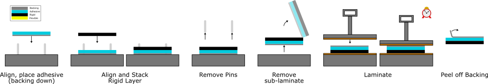
- Place alignment pins in jig at spacing proper for your design
- Lay down adhesive layer 2 upside down (with adhesive side facing up) in the jig
- Lay down rigid layer 1 upside down, so that it matches layer 2’s orientation
- Remove the locating pins from the jig.
- Slide layers off the jig together, taking care not to let them slip against each other and losing alignment
- Lightly laminate layers together
- Remove paper backing from layer 2, taking care not to peel away the adhesive as well.
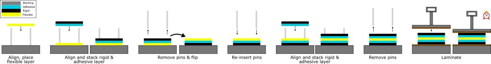
- Place alignment pins in jig at spacing proper for your design
- Place adhesive layer 4 right side up (with adhesive side facing up) in the jig
- Place rigid layer 5 so that it matches layer 4 orientation
- Remove the locating pins from the jig
- Slide layers off the jig together, taking care not to let them slip against each other (losing alignment)
- Lightly laminate layers together
- Remove paper backing from layer 4, taking care not to peel away the adhesive as well.
- Place alignment pins in jig at spacing proper for your design
- Place layer 3 in the jig
- Place laminated layers 4 & 5 in the jig so that it matches layer 3 orientation
- Remove the locating pins from the jig
- Slide both layers off the jig together, taking care not to let them slip against each other (losing alignment)
- You may laminate briefly to tack these layers down if they are prone to slipping (typically don’t need to)
- Carefully flip layers 3,4&5.
- Place alignment pins in jig at spacing proper for your design
- Place layers 1&2
- Place layers 3, 4 & 5 in the jig so that it matches the orientation of layers 1&2.
- Remove the locating pins from the jig
- Slide layers off the jig together, taking care not to let them slip against each other (losing alignment)
- Laminate layers together, keeping on the press to securely bond all layers.
Step 3: Second-Pass Cut
If you followed these instructions, the rigid material scrap should still be taped in place in the bed of the laser, with the second pass cut aligned with the hole created by the first-pass cut.
Alternately, you will need to make a new jig. Place a new piece of rigid material in the bed and tape it down. Run your second pass cut file on the rigid layer material. This should remove the outer profile of the laminate. Remove all inner material leaving the outline of your laminate. This creates a jig to be used in the final cut. Put the laminate stack in the hole created at the end of the first pass cut.
Before running the cut at full power, it is advisable to run a test cut to ensure that your jig aligns the material well. Try running at a low power, high speed setting to trace a path on the top of the laminate for inspection. Check around hinges to ensure that the cutout fully removes all connected material.
Your laser cut settings for a full laminate should be slower and / or more powerful than the cut settings for your most difficult-to-cut individual layer. For example, if your rigid material requires 100% power and 20% speed to be fully cut out, try setting your second pass cut setting to around 100% power, 10% speed as a first guess. It will have to cut through at least twice the thickness of your thickest layer, and has to deal with focus issues that crop up in thicker materials.
Repeat passes as needed, incrementally increasing or decreasing cut power and speed until you get the desired cut depth.
If your laminate is thick or you have a short focal length lens, it may be worth considering raising the bed in order to bring the bottom plane of the material into better focus. This can often be commanded directly from the cut settings in the printer preferences.
Before fully removing your part, ensure that the final device has fully been separated from its support. This can be often seen with the naked eye as the laser closes a given path (the part actually falls out a bit), or checked by gently trying to remove the inner part. It is easier to cut multiple passes before moving it than after you have touched it, though. Moving the part can lead to mis-aligned cuts
Remove and assemble
Once the laminate is removable, you may take it out of the laser and assemble it.
Step 4: Clean up your Area
- Turn the temperature of the press back to its normal setting
- Clean all scrap material. Return big unused scrap, throw away small scrap
- Turn off air supply to laser(if applicable)
- Turn off laser(if applicable)
- Turn off vacuum to laser (if applicable)
- Put away all tools including scissors, focusing tool
- Clean files off the desktop and sign out