Solidworks is an attractive way to model popup devices because you can interact with the three-dimensional kinematics of your popup device. However, Solidworks is not good at everything. First, it cannot create your cut-files for you automatically. Solidworks knows nothing about how you’re going to make your device, out of how many layers, and with what manufacturing processes. Second, Solidworks is such an expansive tool, and can be used in so many different ways that the most straightforward way to design a popup device is not very obvious.
So, to help users with these issues, we have outlined a workflow which can be used to rapidly create a popup device whose kinematics you can visualise and interact with quickly. Second, we also outline the steps to export those basic multilayer kinematics to a popupCAD file so that the manufacturing specifics can be done in an environment with built-in manufacturing knowledge.
Download example.zip to see this example project.
Step-by-step Instructions
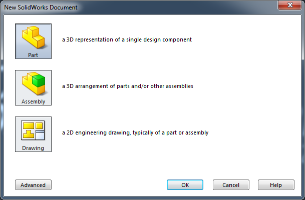
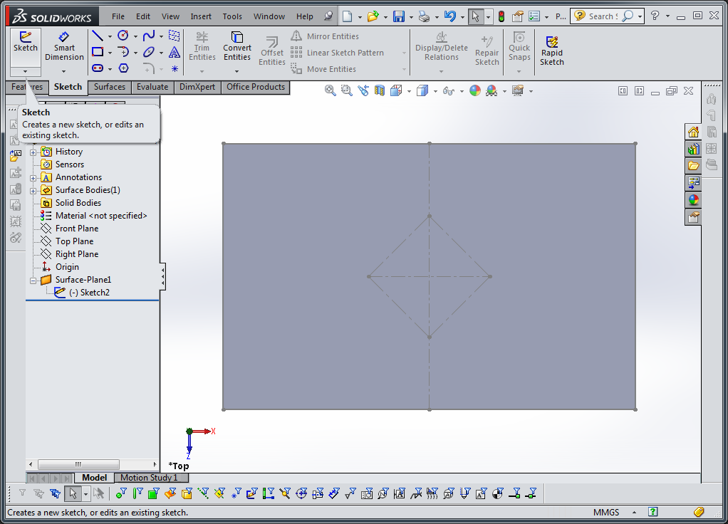
Create a new part file
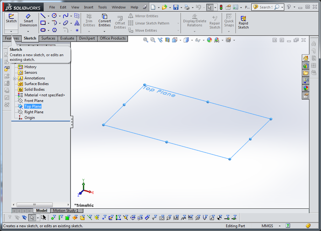
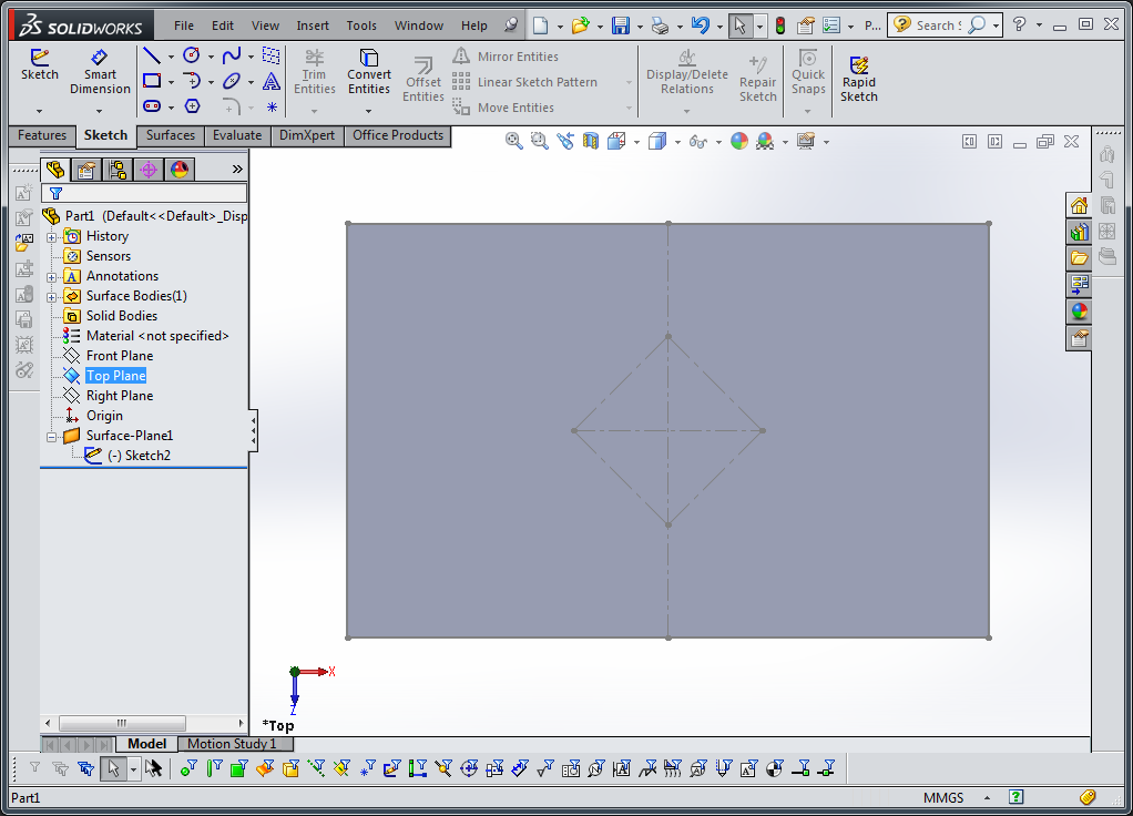
Select a reference plane(top, for example) and then create a new sketch (or create a new sketch and select any reference plane)
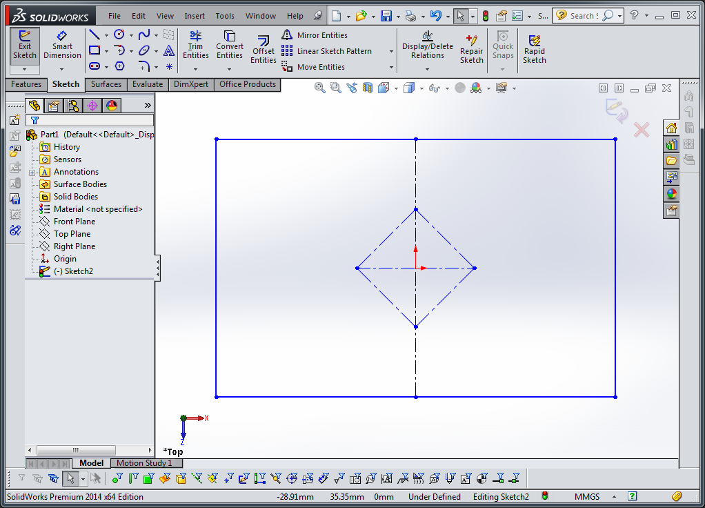
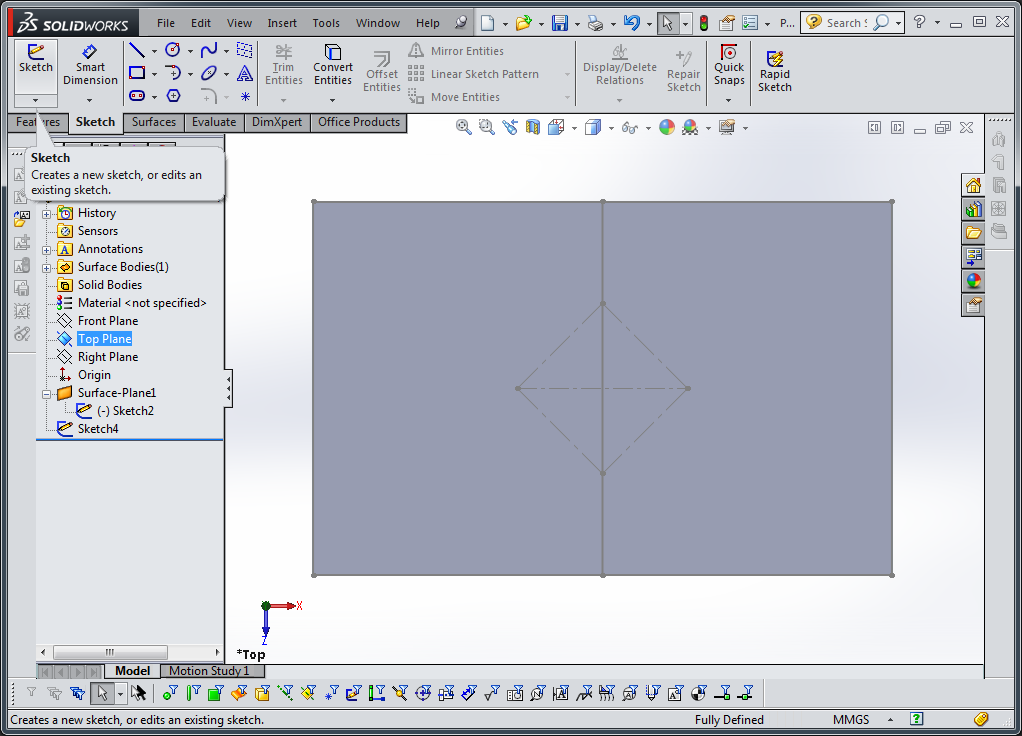
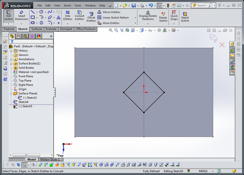
Sketch the lines which define your robot. The outline of your robot should be a drawn out of solid lines. Any internal hinges should be drawn as construction lines, or made into construction lines once drawn. If you are making a robot which consists of multiple sub-laminates, you should create one of these sketches per sublaminate.
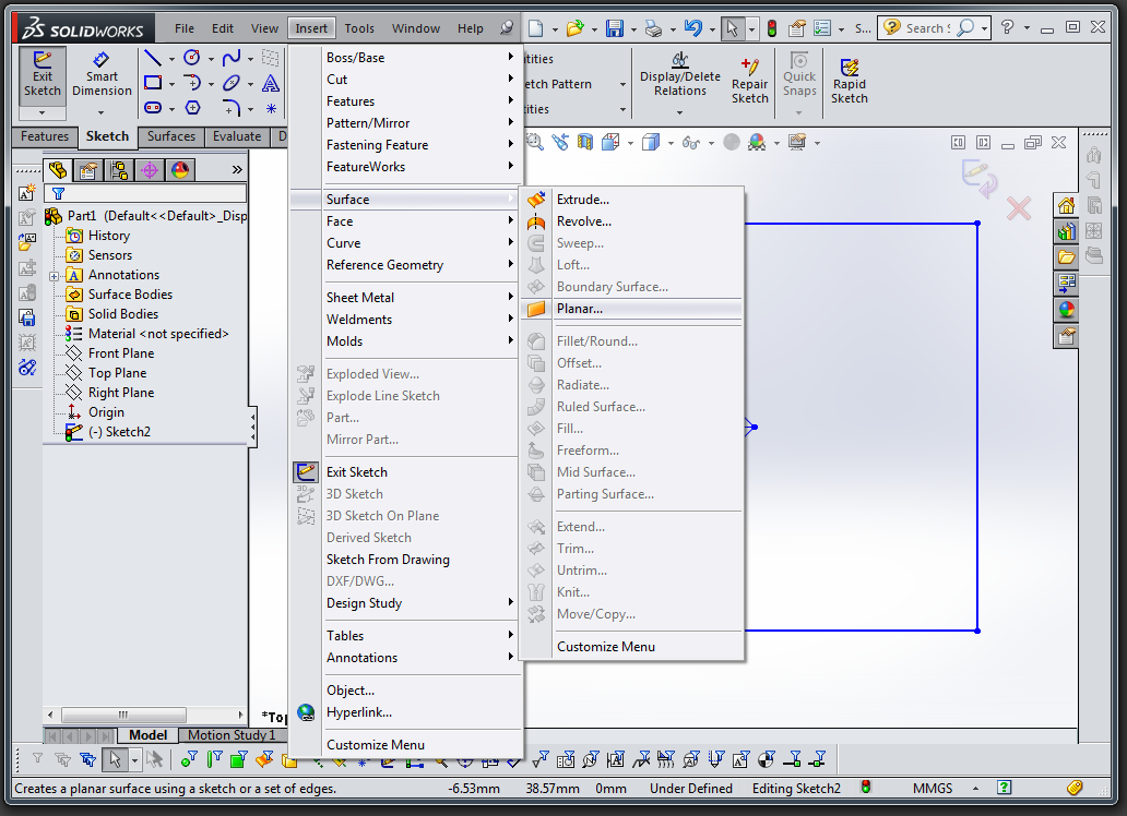
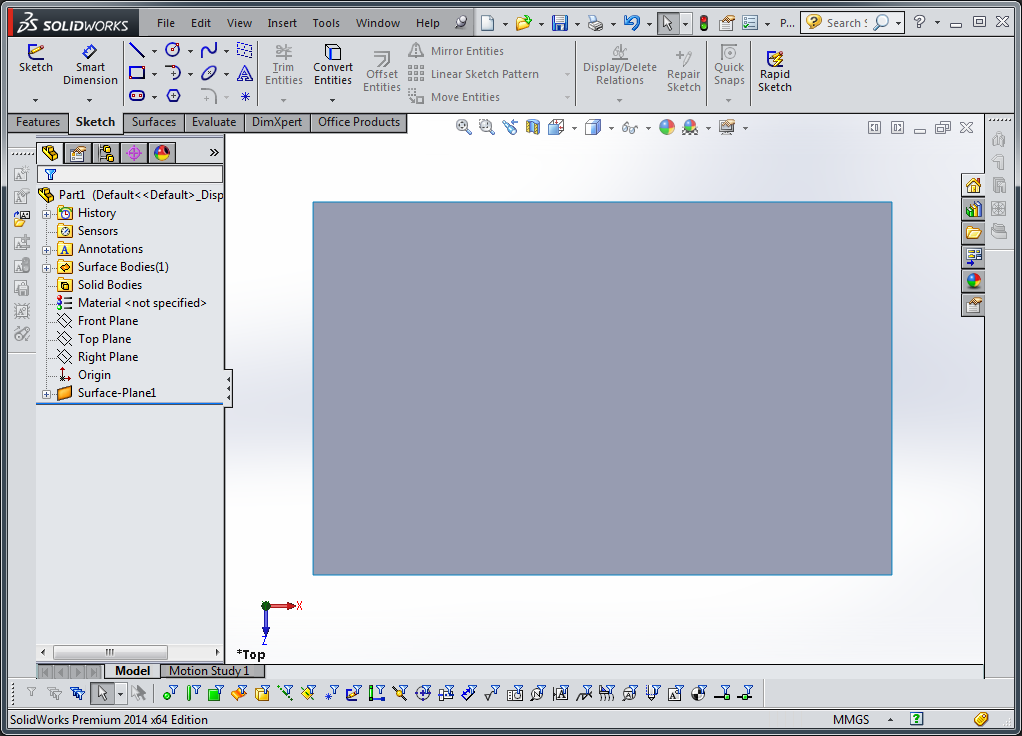
Next, for each sub-laminate sketch that you have created, you can should create a planar surface. Go to insert->surfaces->planar surface. Select each sketch. This should create a surface whose outline matches the closed shape of solid lines you drew in your sketch.

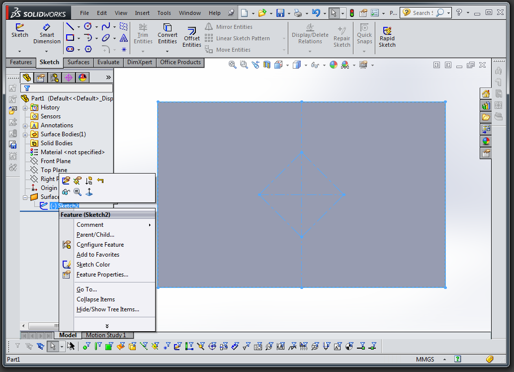
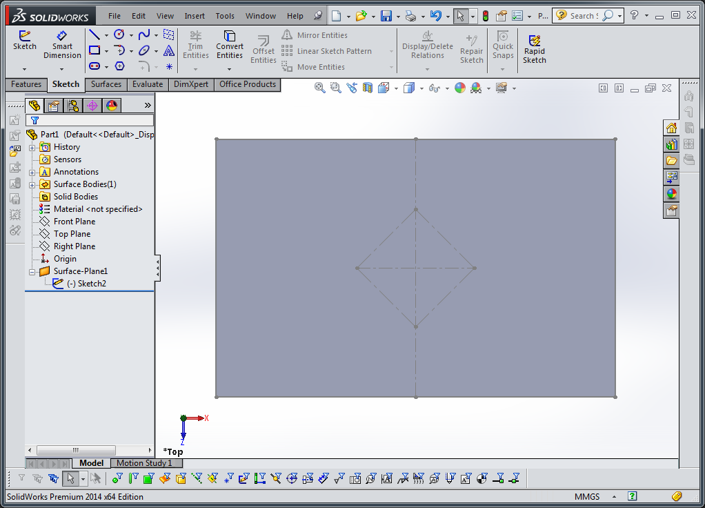
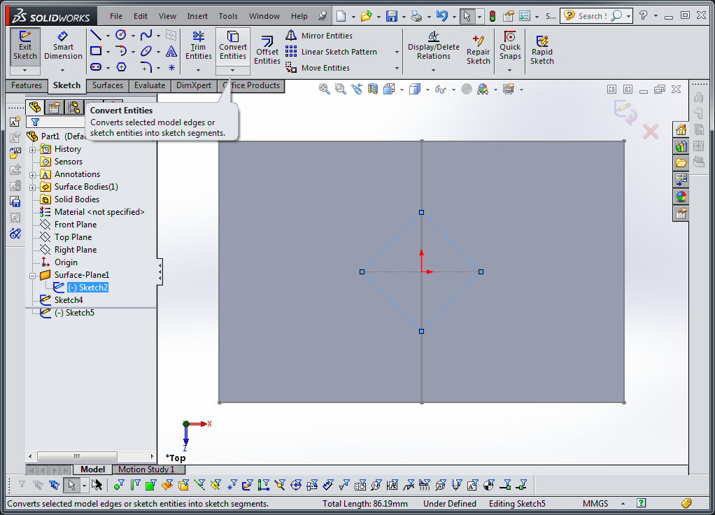
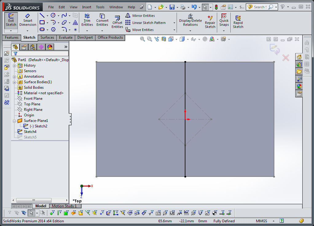
For each surface you just created, you want to split that surface along all the lines representing joints from your original sketch. First, unhide the original sketch by clicking on the eyglasses icon under the surface->sketch in the left project pane. This will allow you to view, select, and reference lines drawn in that sketch.
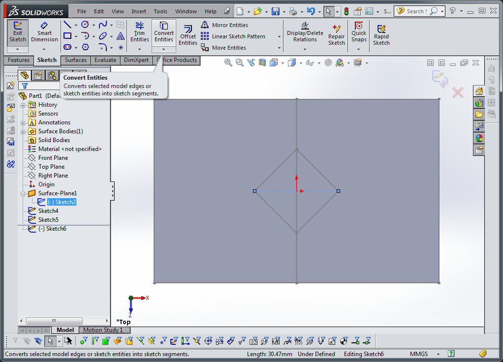
Next, create a new sketch on the same reference plane(such as the top plane), select one or more joint lines, and in the sketch tools, select “convert entities”. Only select sets of lines which do not cross each other, as the next step will fail. Make sure that the lines you do select completely cross the surface, or create a loop.

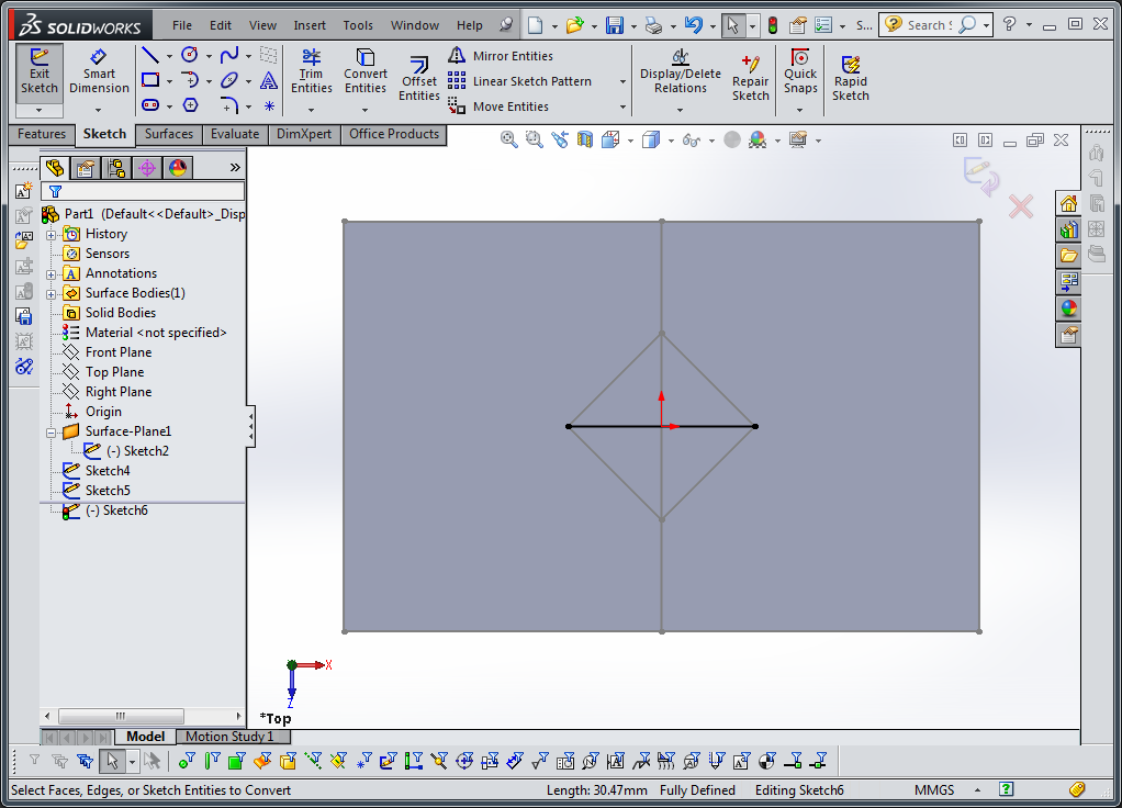
Repeat the last two steps for the remaining joint lines, making sure not to select sets of lines which cross each other or more than two lines at any point.
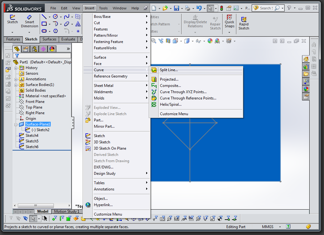
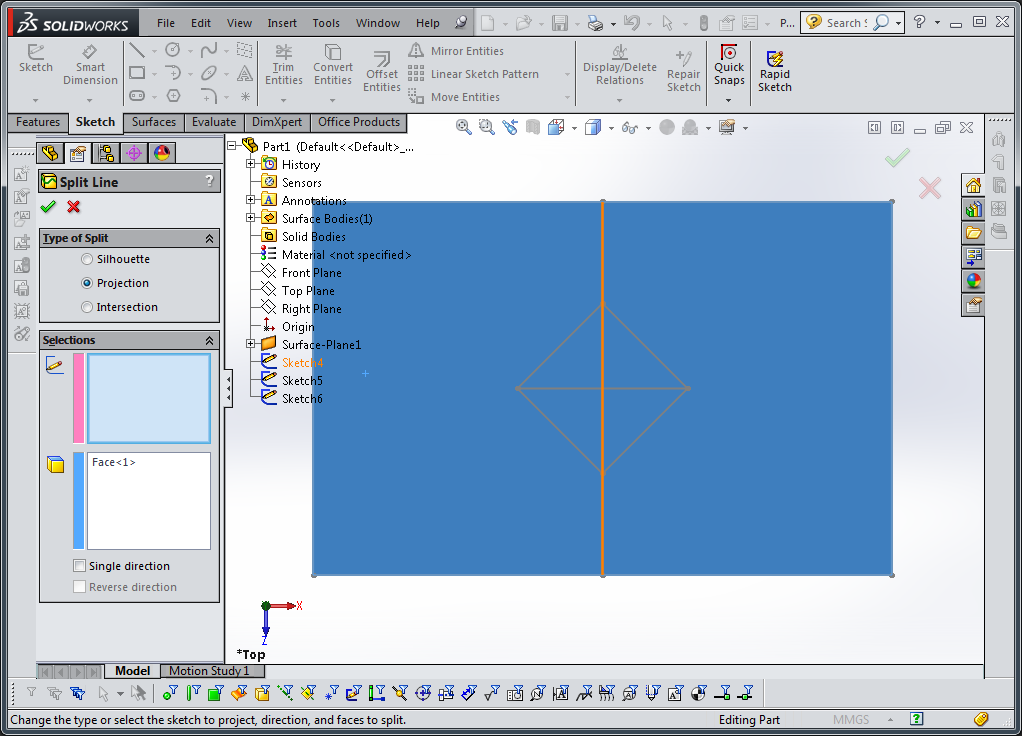
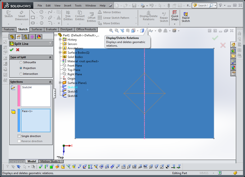
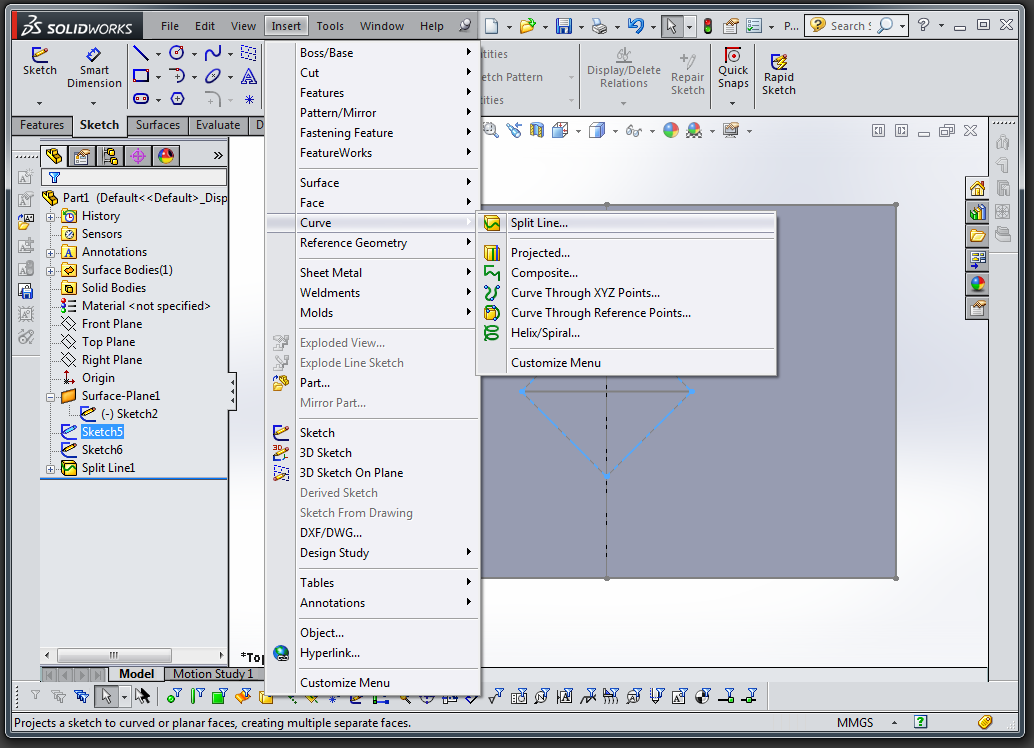
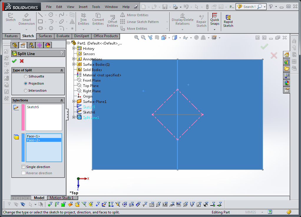
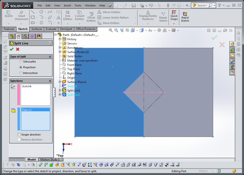
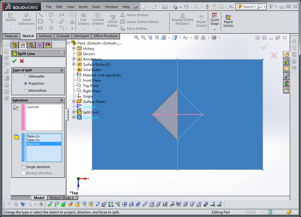
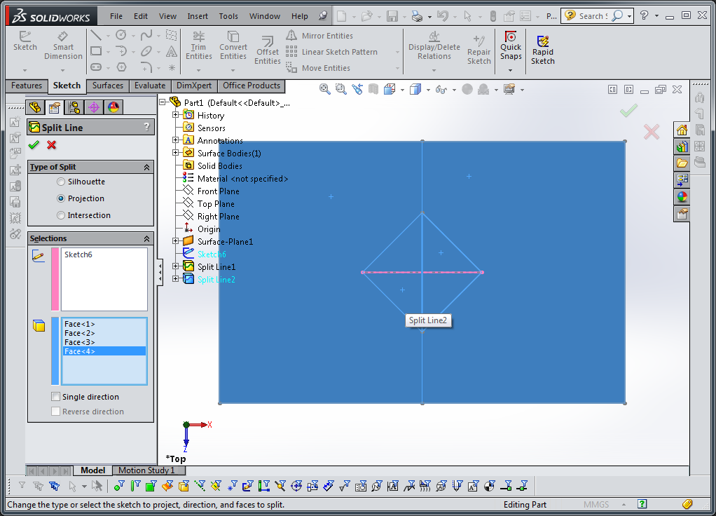
Use insert->curve->split line to separate faces. You will need to do this for each sketch you just created. When you do this, remember to select all the surface faces to ensure they get split by the sketch.


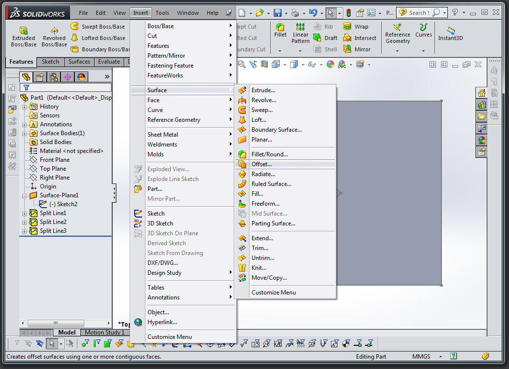
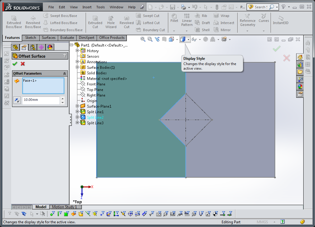
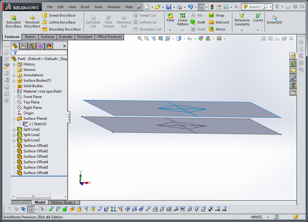
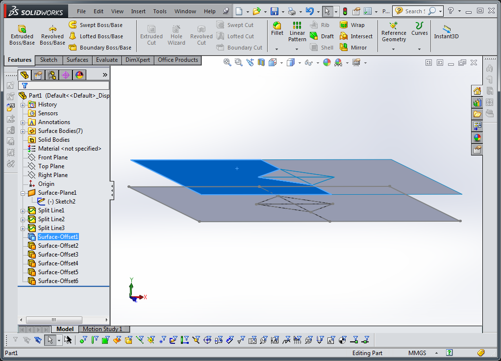
Use the insert->surface->offset function to create independent surfaces from faces of original body. Hint: to repeat creating the same feature over and over, hit enter after creating one offset surface feature and solidworks will begin a new one.

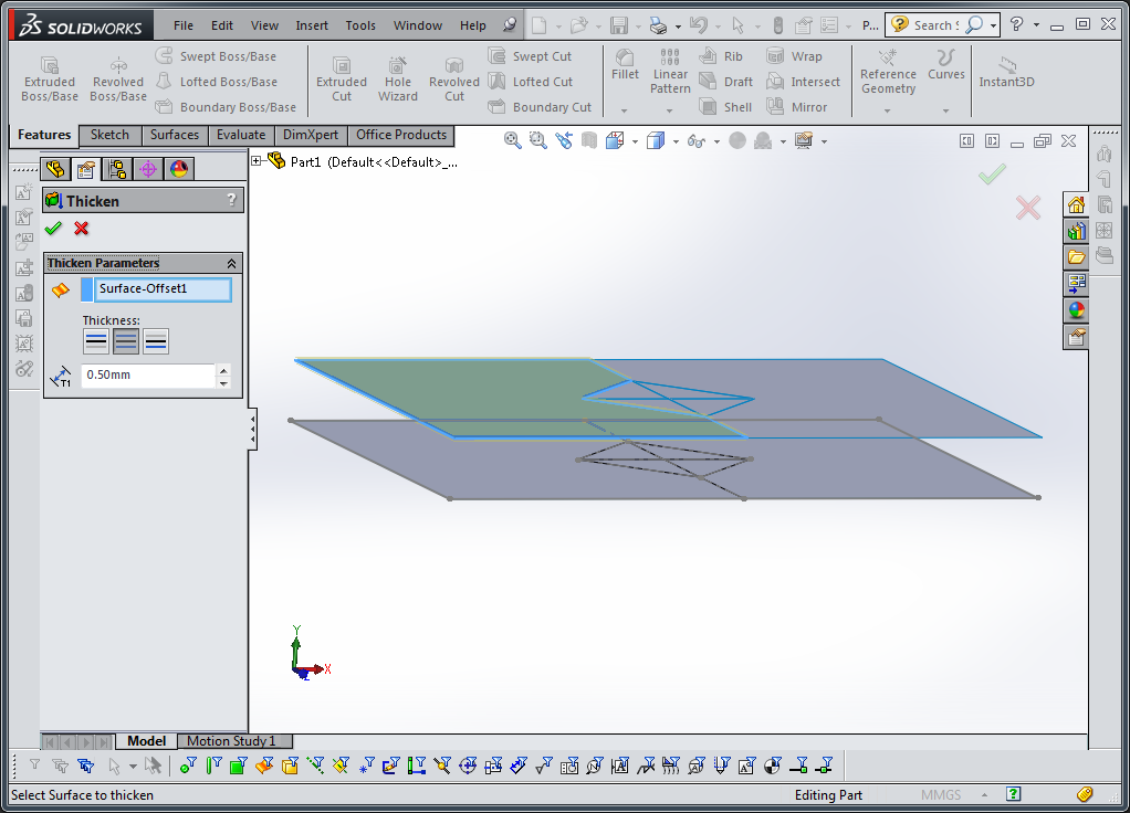
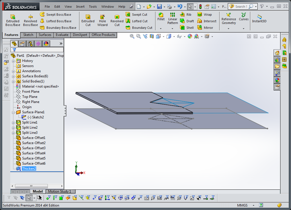
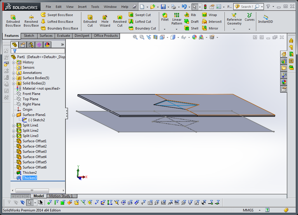
Use insert->boss/base->thicken feature to thicken each feature. Hint: deselect the merge body option after creating the first thickened part, otherwise the bodies will merge back together.


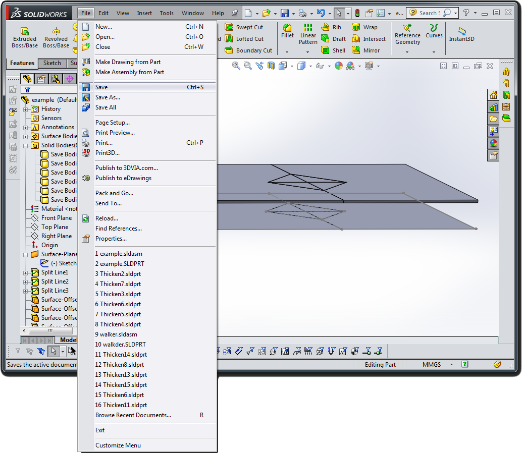
Save your file!!
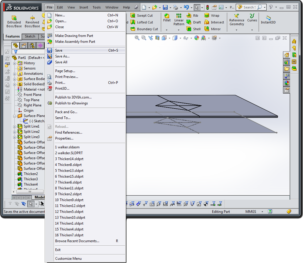
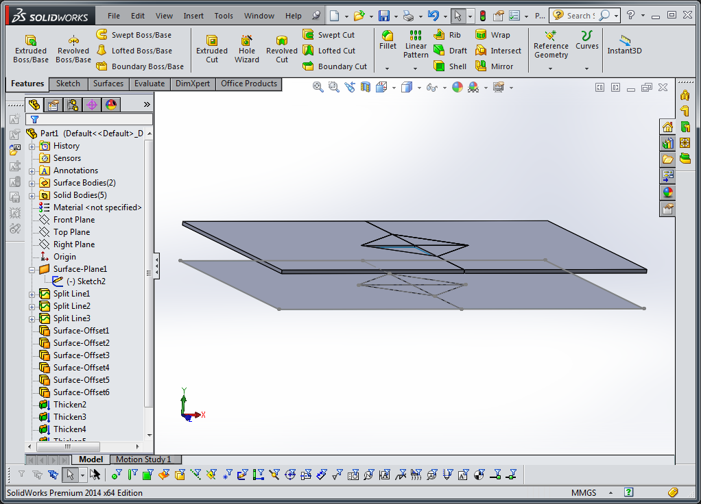
Look at the project menu on the left. You should have a number of solid bodies in your part file.
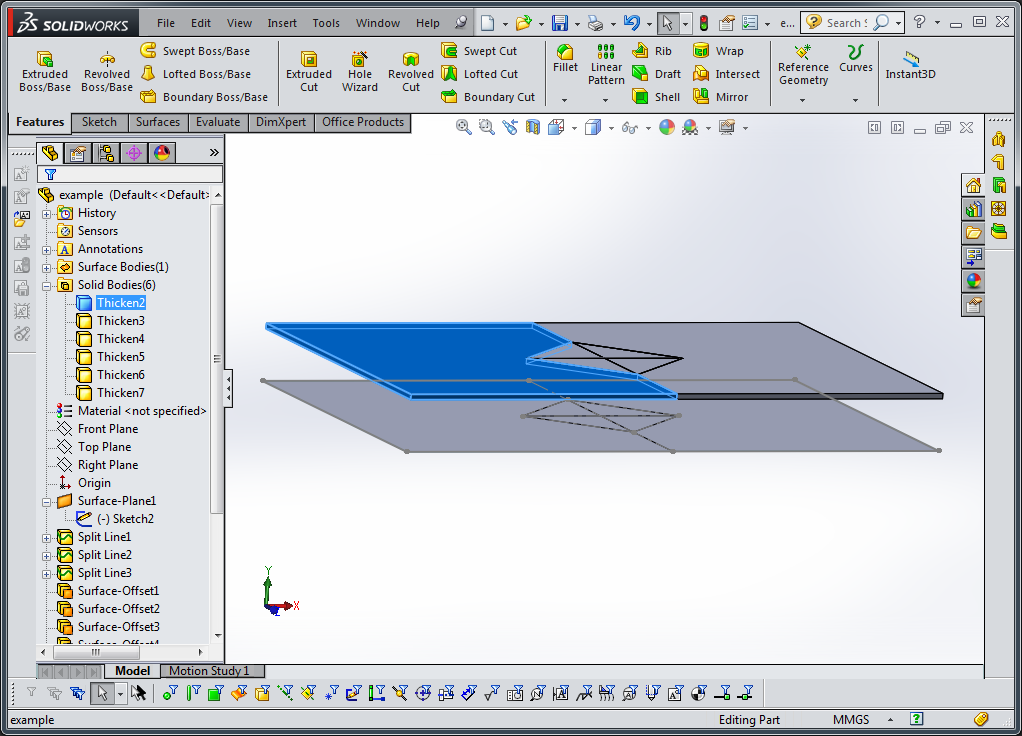
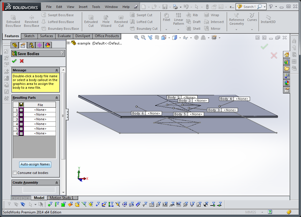
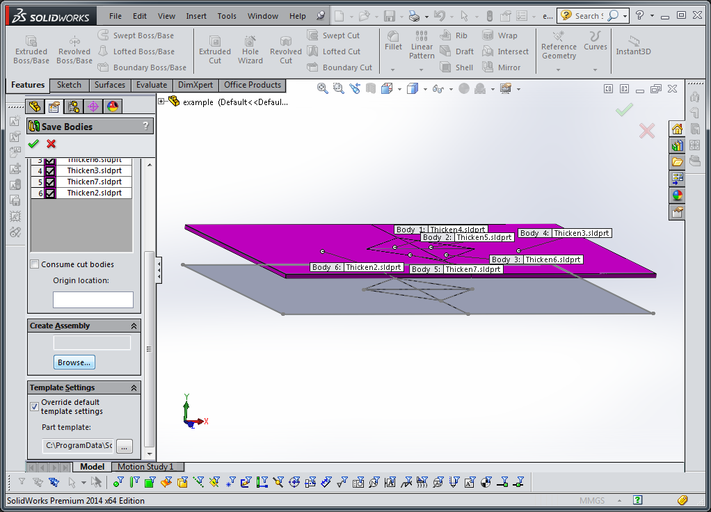
Right click on the solid bodies folder and select “save bodies”

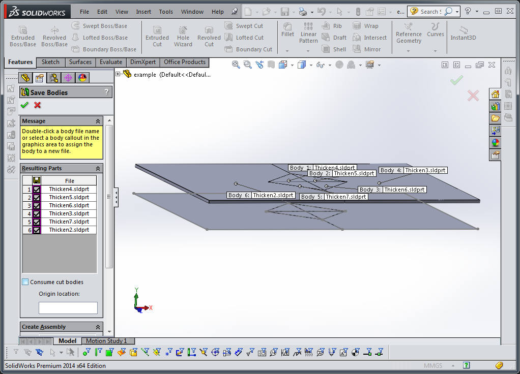
In the save bodies menu, auto-assign names and select an assembly name. This will automatically put all the saved bodies into an assembly file. Click the green check box. Select “rebuild” if a notification box pops up. This should begin the save process and open up your new assembly file in the background

Save and close your part file. Now the newly-created assembly file should be visible.

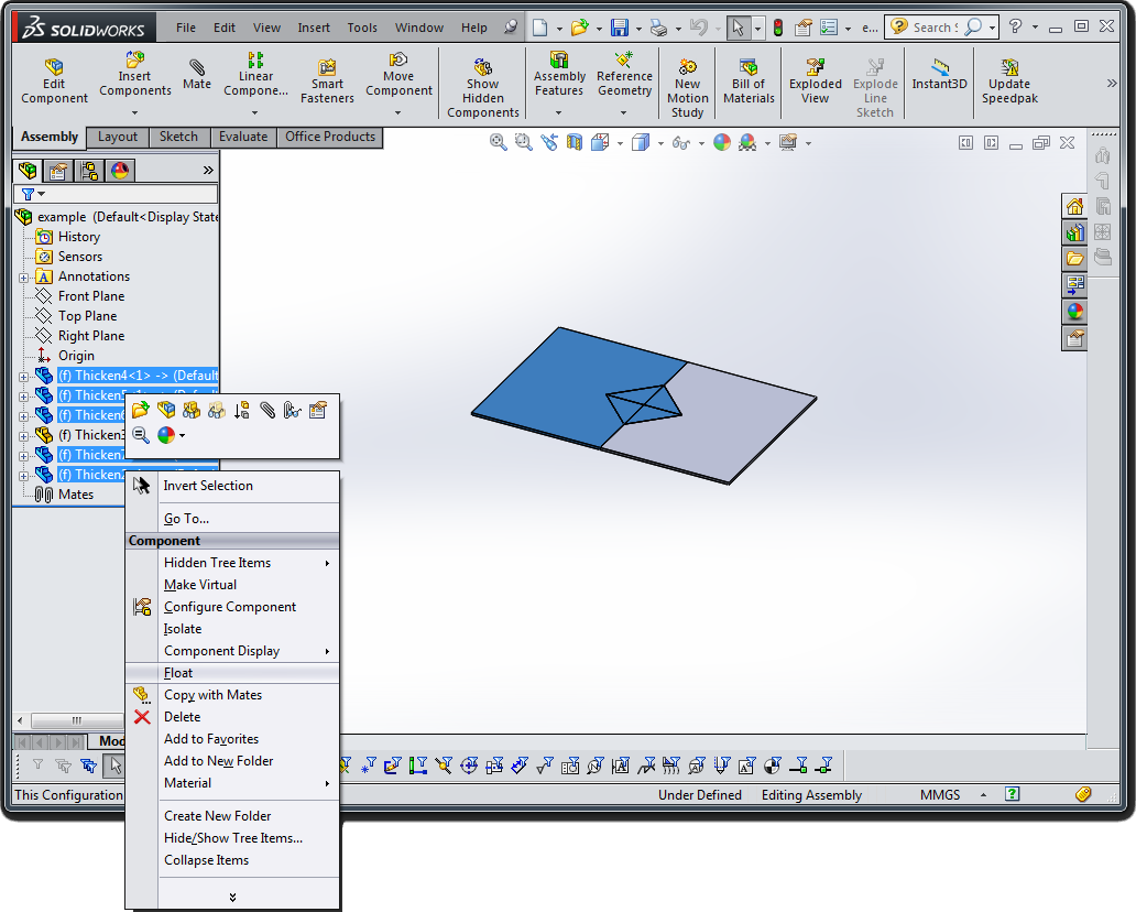
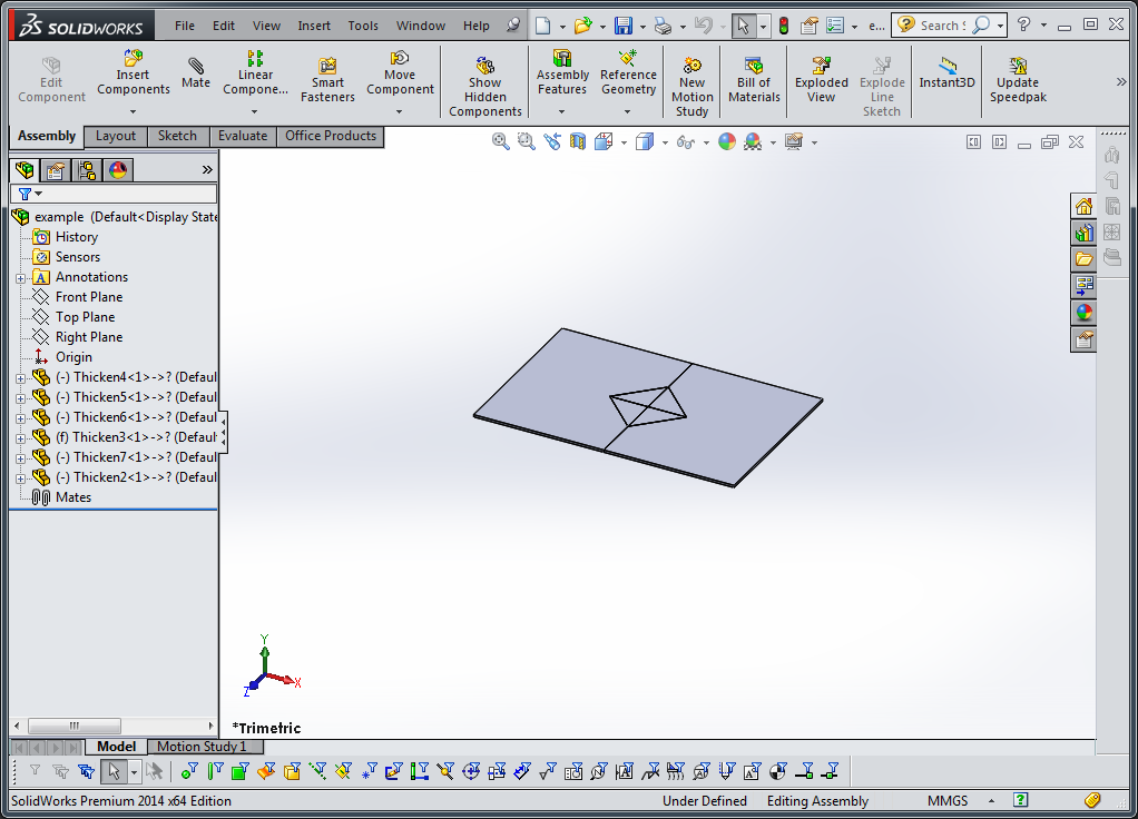
All the parts in your assembly are fixed in space relative to each other. To visualize how they will move, you must float all the parts except for one. To do this, select all the parts you wish to be able to move, right click on them in the project manager on the left, and select “float”. These parts should now be able to be moved by dragging them.


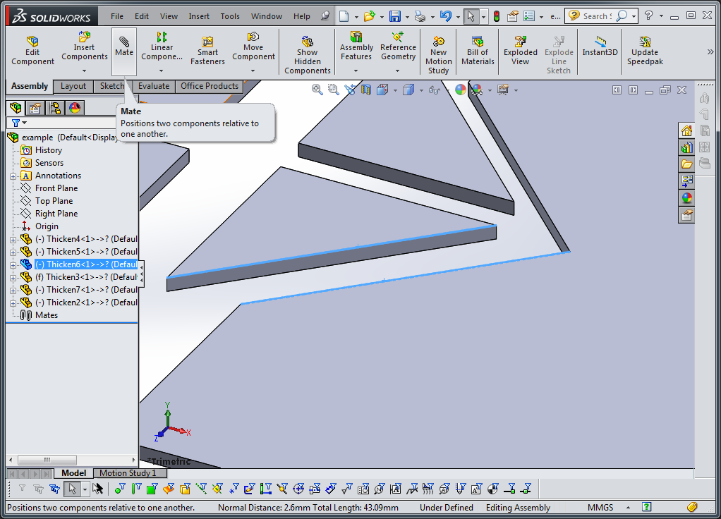
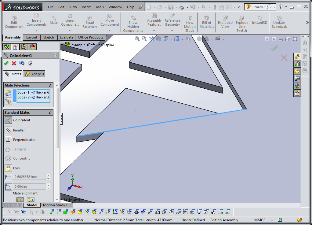
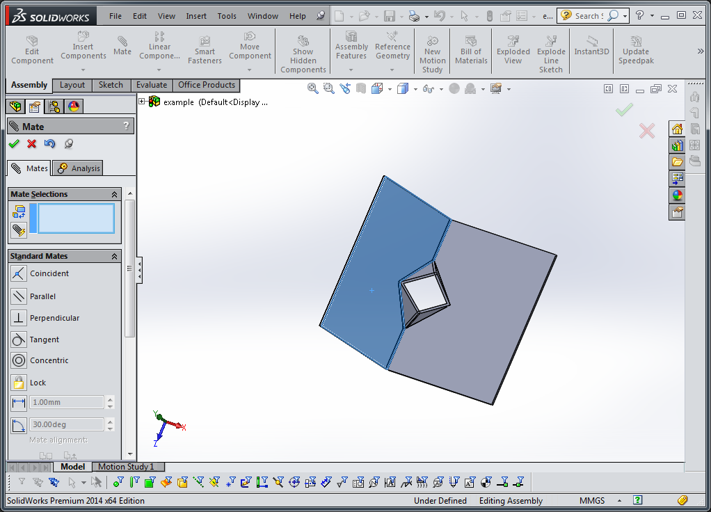
Next, you must create mating conditions to define the joint kinematics of your devie. Since these thickened flat sheets represent several layers laminated together, they will most likely rotate around their midplane. However, to assemble the device faster, it is easier to select edges and points on the top or bottom surface, with the knowledge that it may not move exactly the same in real life. Select one mating line on two parts you would like to joint with a joint and then select the “mate” button in the assembly tab. This will bring the two lines together. Hit enter to accept
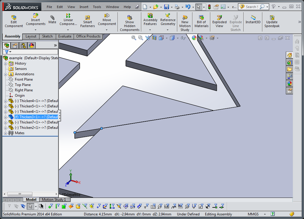
Next select two points at the end of the mating edge you just joined, one for each part. This should join those two points and constrain the parts as if they are joined by a hinge. You can now move those two parts relative to each other.

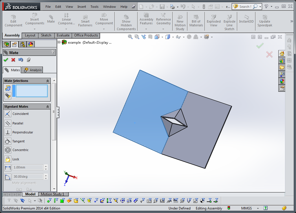
Repeat this process for each joint you wish to create. This should fully define the motion of the device. You can move the device around as it will work once created, as in this video

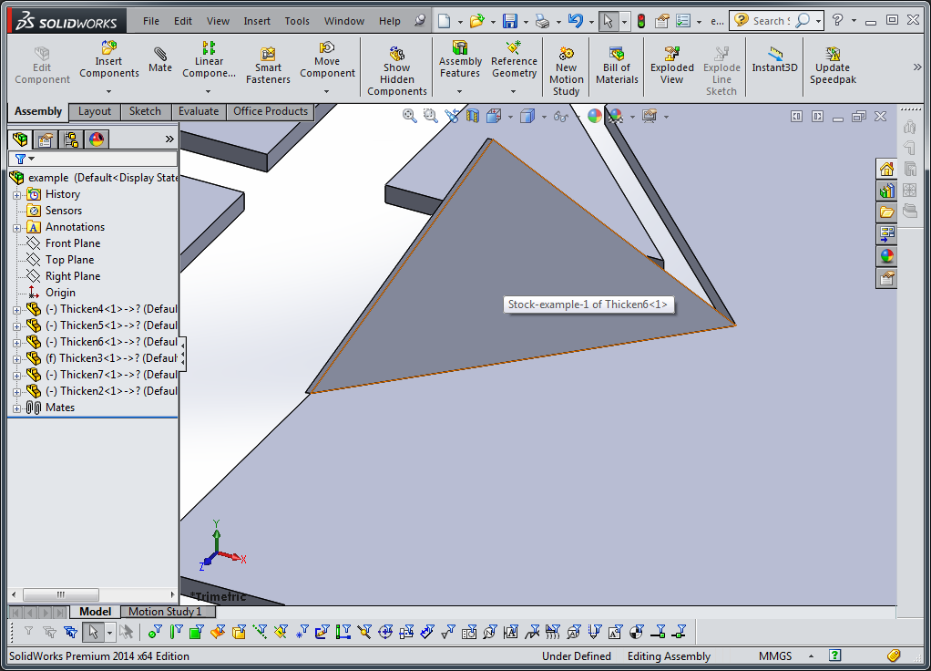
Once you have defined the kinematics of the device, you must now re-flatten the assembly so that you can export it to popupCAD. Add additional mating constraints to neighboring faces of your device, making them “coincident” to each other. This will flatten it.
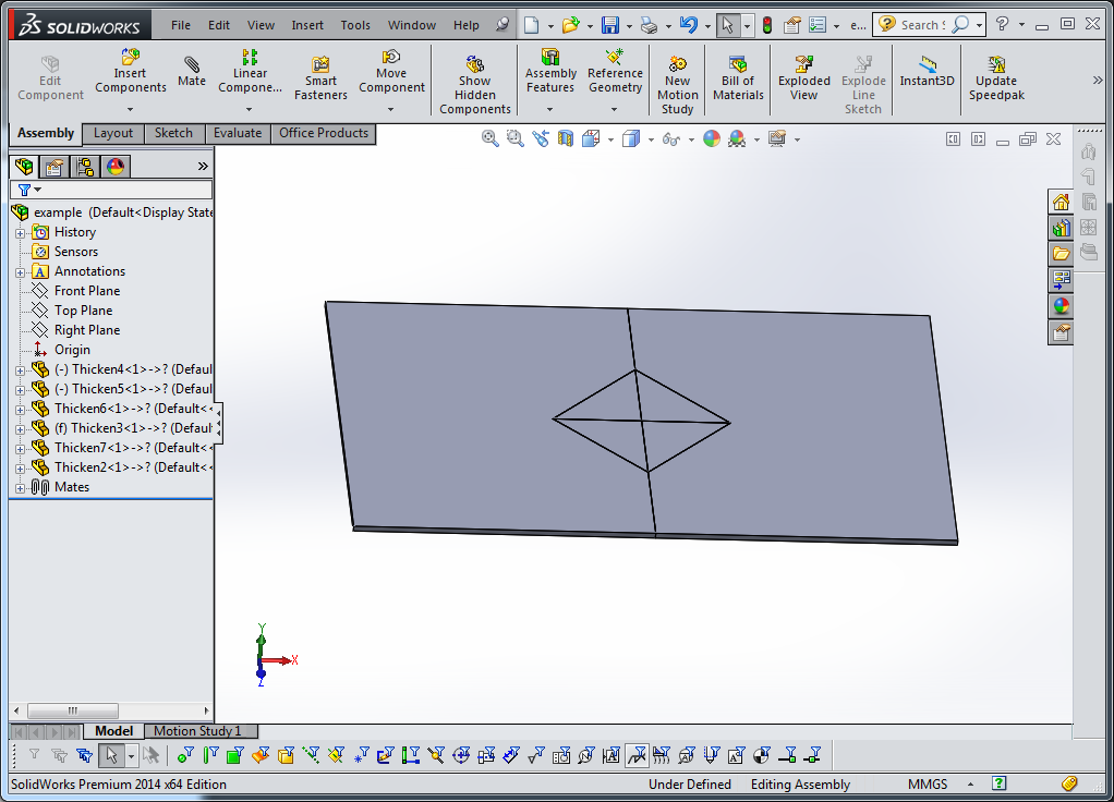
Save your Assembly
Next…
Continue to export this assembly to a format you can read in Python with the Solidworks Export Tutorial)