A popular way of deriving the desired kinematics of a device graphically has also been employed for centures.
By Hand Instructions
Download the [part]({{ .site.Params.home }}/assets/graphical-synthesis/part2.sldprt)
The following instructions can be done by hand or with a tool like Solidworks. If you do it by hand you will need a ruler and straightedge.
Draw a constant length line (the output link) in three different positions.

Joint 1
Draw a line from the left vertex of the output link in position 1 to the left vertex of the output link in position 2


Draw a line from the left vertex of the output link in position 2 to the left vertex of the output link in position 3
Find the perpendicular bisector of these two lines. Where they intersect is the location of joint 1
Joint 2
Draw a line from the right vertex of the output link in position 1 to the left vertex of the output link in position 2

Draw a line from the right vertex of the output link in position 2 to the left vertex of the output link in position 3
Find the perpendicular bisector of these two lines. Where they intersect is the location of joint 2
Links 1 and 3
The next step is to draw the coupling links.
Draw lines from joint 1 to the left vertex of the output link in position 1, 2, and 3
Draw lines from joint 2 to the right vertex of the output link in position 1, 2, and 3.

Measure the length of your output and coupliing links, as well as the distance between joint 1 and 2 (this is the base/fixed link). This is your four-bar design
With this design, a body will be guaranteed to move through these three positions.


This graphical synthesis method is simplified, because there are more design variables at your fingertips than this rudimentary method permits…it just gets too complicated to solve for graphically.
Solidworks Instructions
Download the [part]({{ .site.Params.home }}/assets/graphical-synthesis/part1.sldprt)
If you want to use the ability of Solidworks to add constraints to objects, this can simplify the process. Below are the steps.
Create a new part

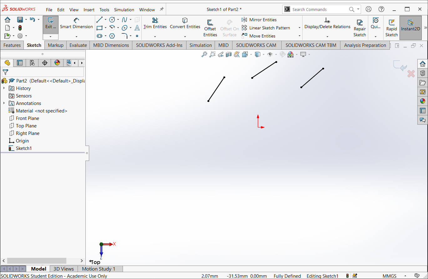
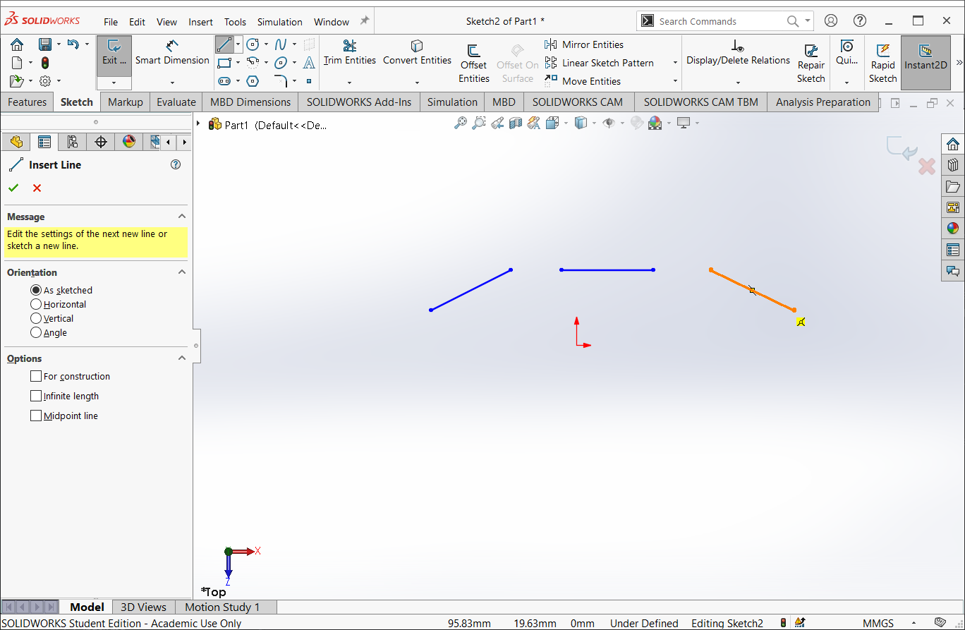
Select the top plane and create a new sketch
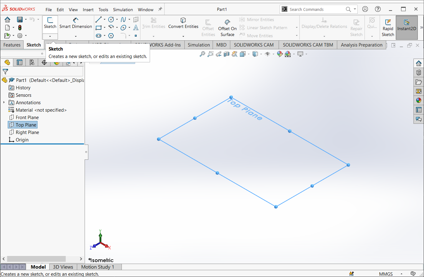
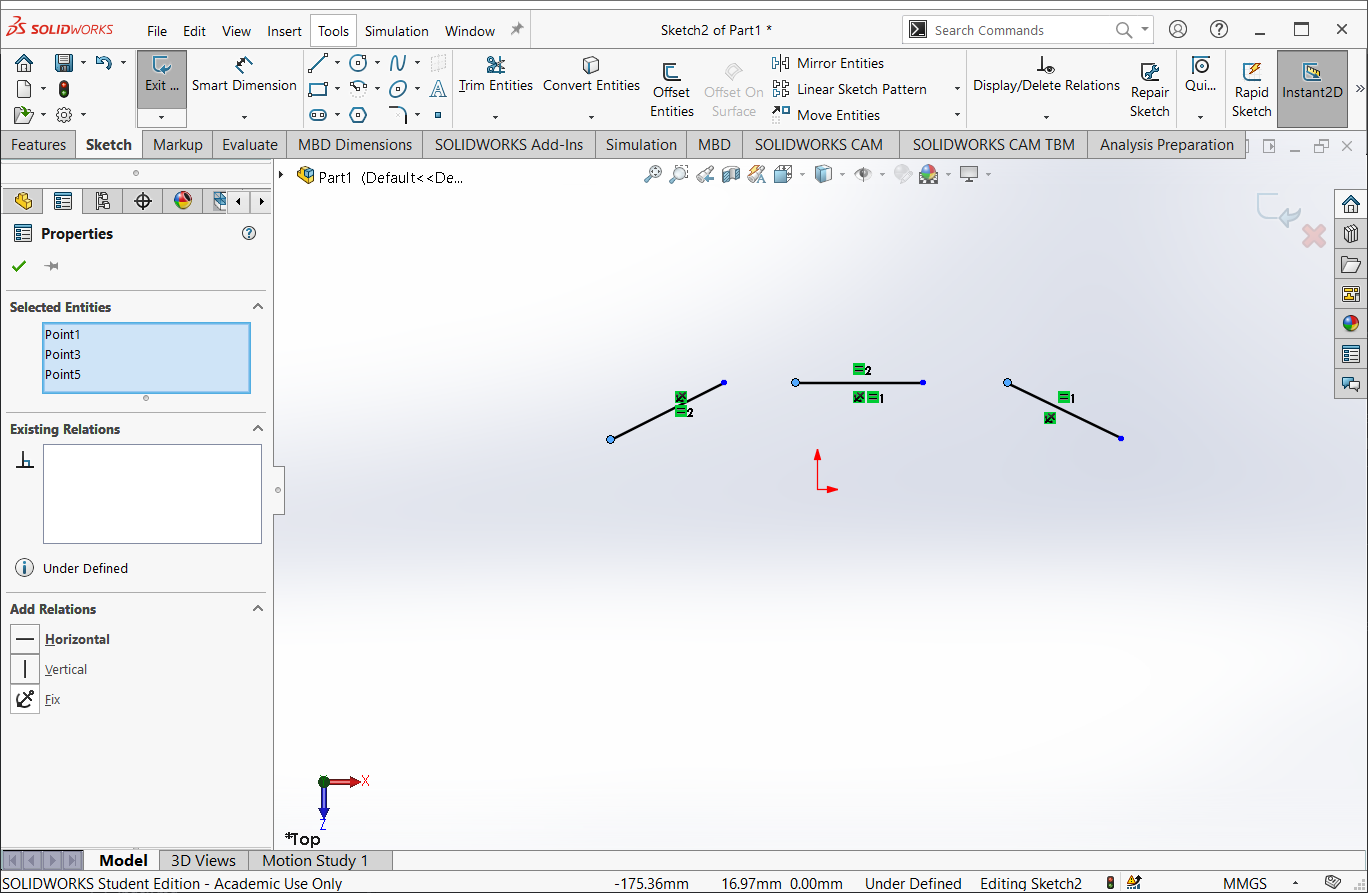
Draw three lines
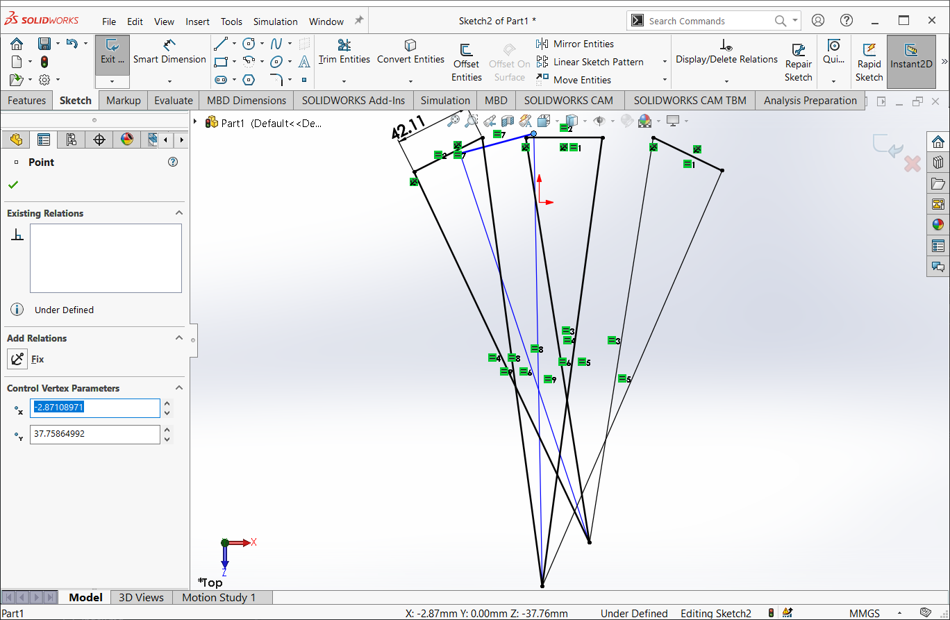
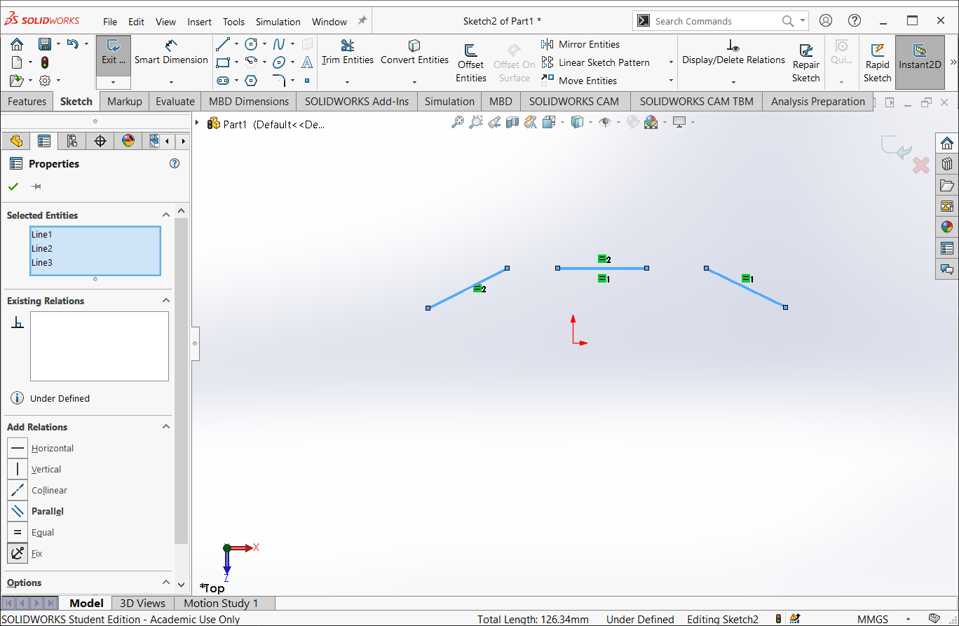
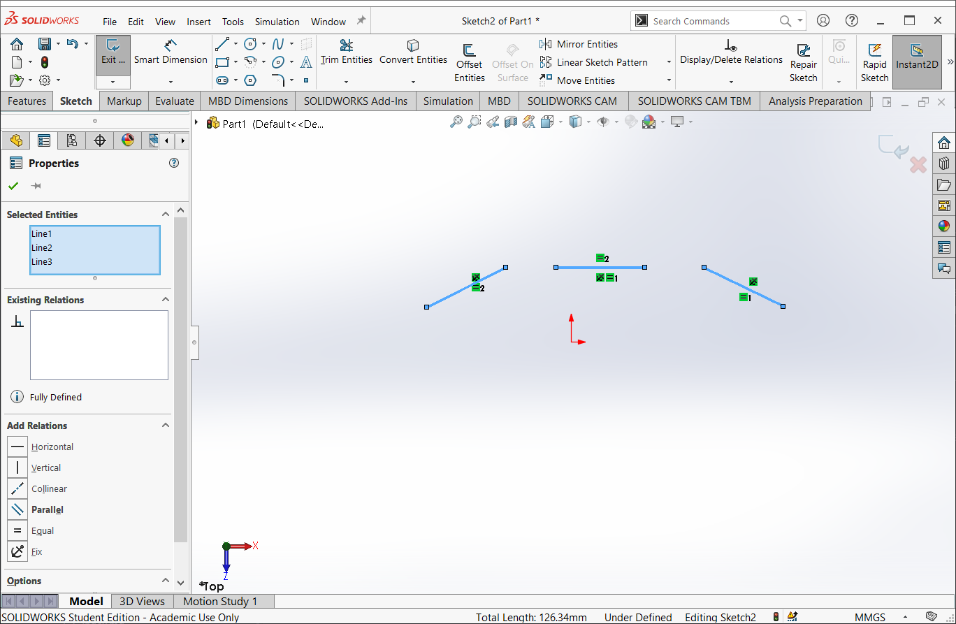
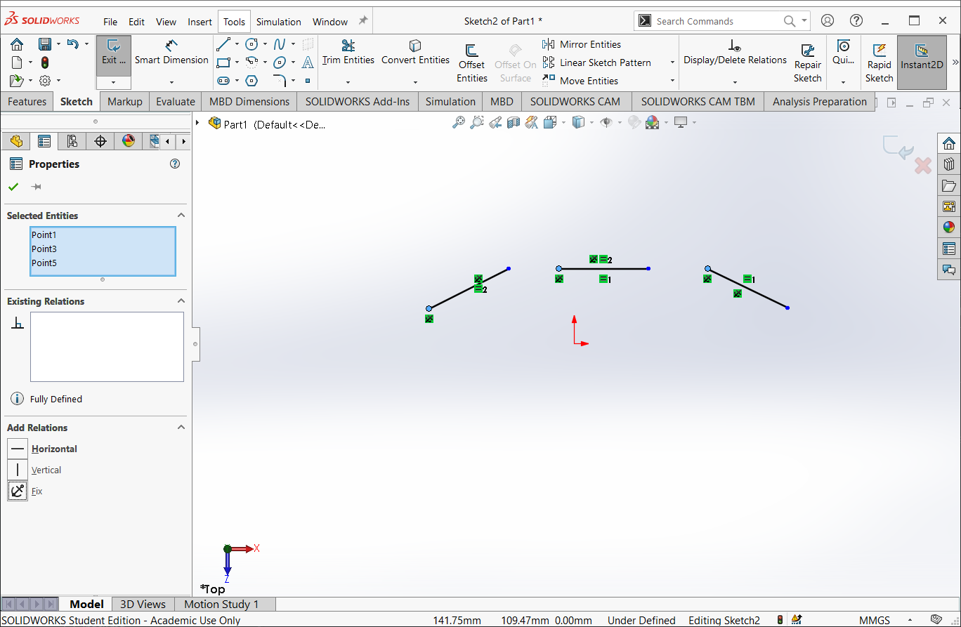
Select all three lines and add a constraint to make them equal length


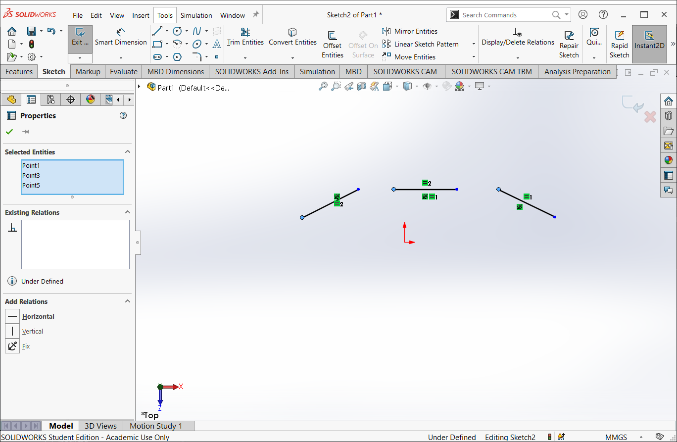
Select the left vertex of each line and apply a “fixed” constraint
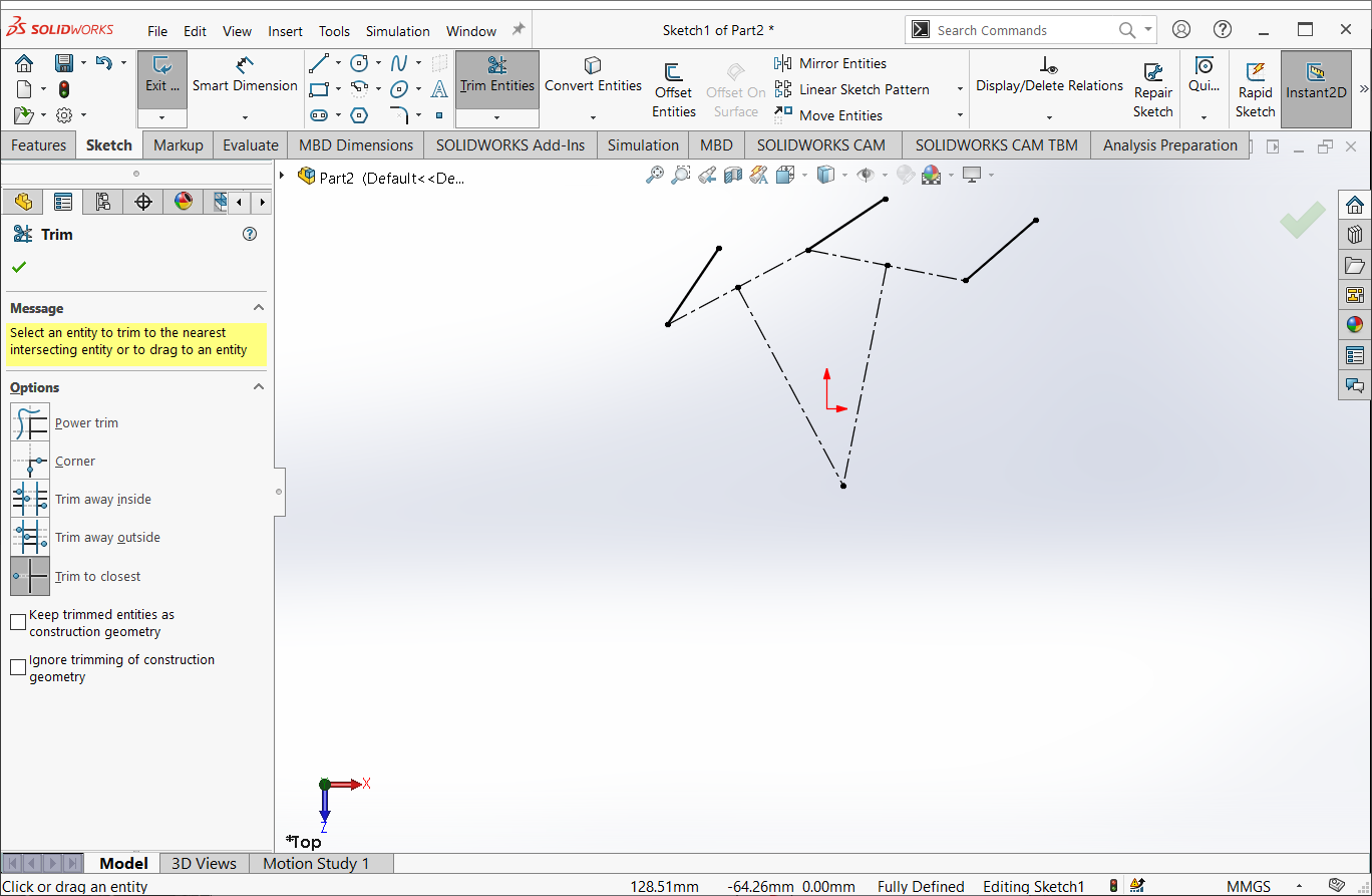
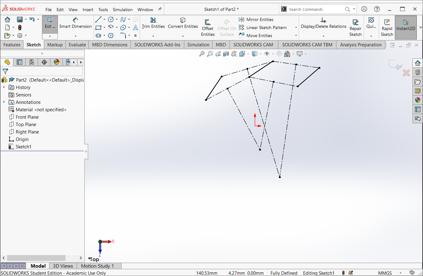
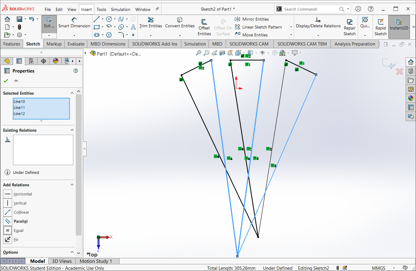
Starting with the left vertex of each line segment, draw three lines that meet at a common point
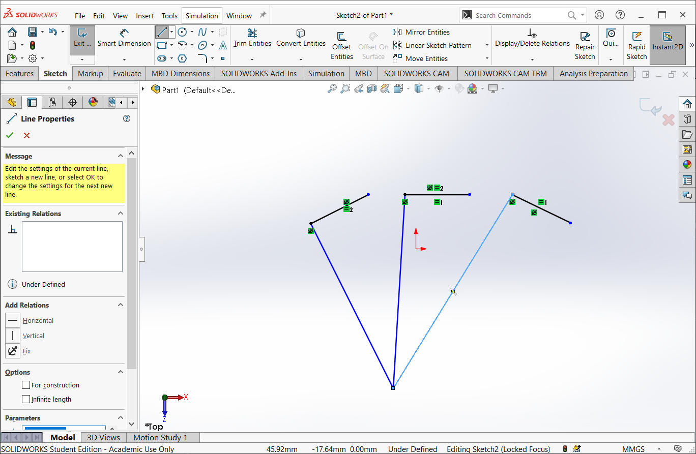
Select all three lines and add an “equal length” constraint

Starting with the right vertex of each line segment, draw three lines that meet at a common point
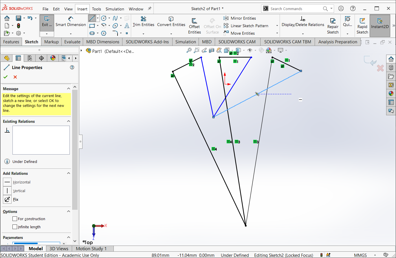
Select all three lines and add an “equal length” constraint

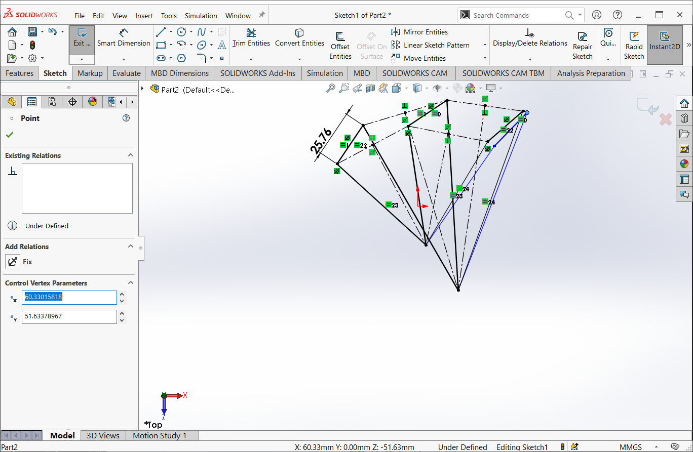
Establish three equal length constraints with the corresponding line segments
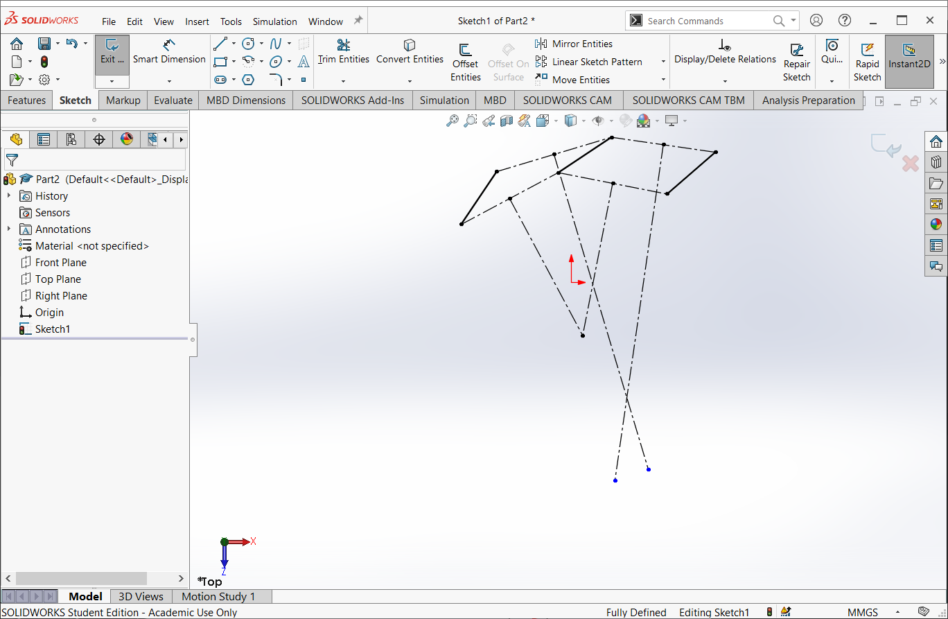
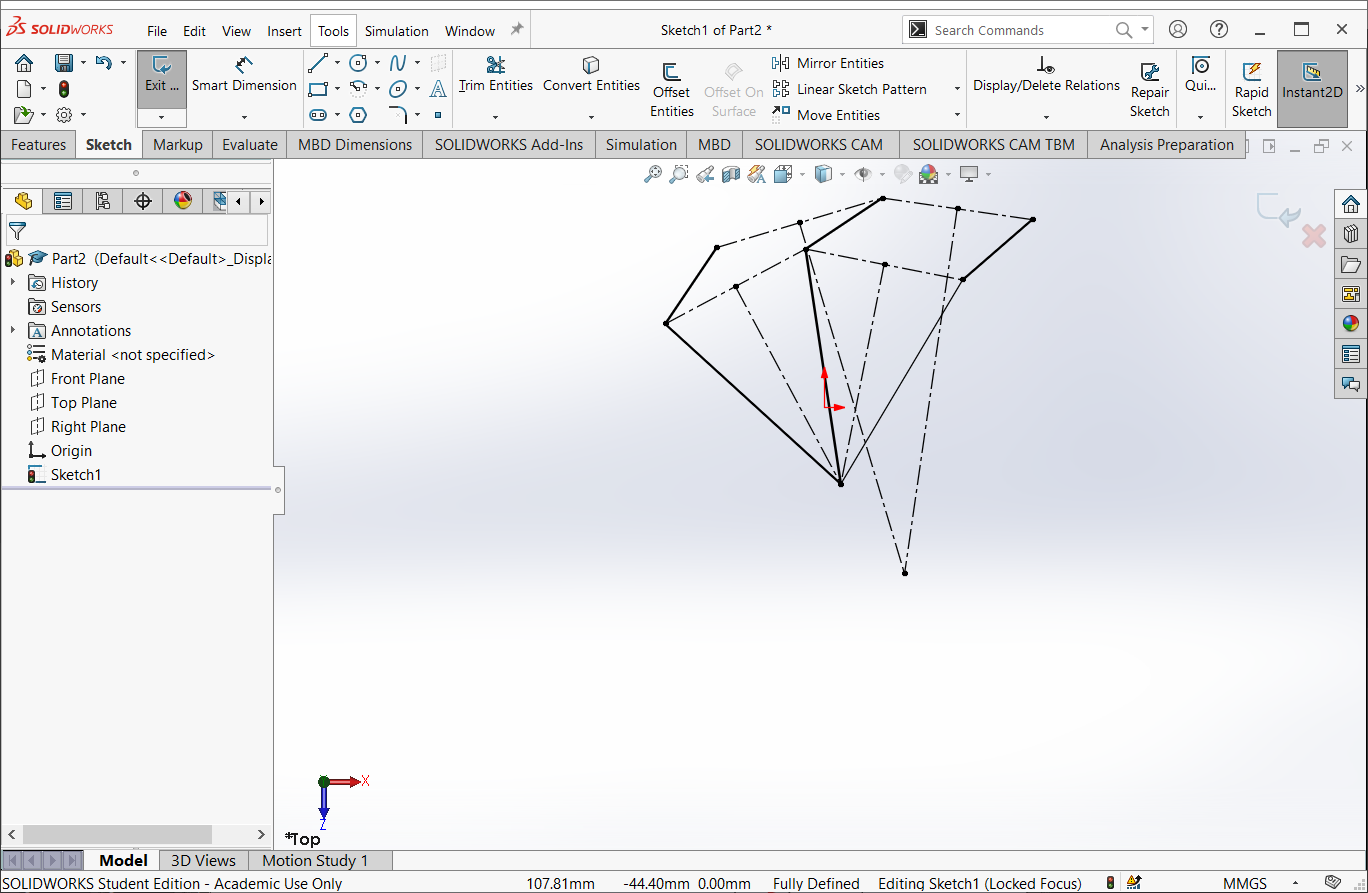
Add a fourth line segment and connect its left and right vertices to each of the common points.
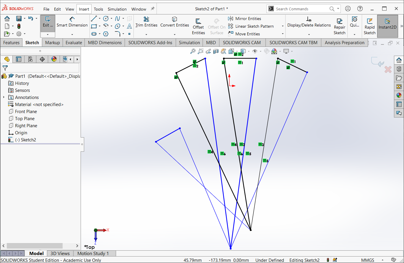

Dimension the length of the line segment

Select and drag the new line segment. It should be able to move through each of the three positions you defined