Steps
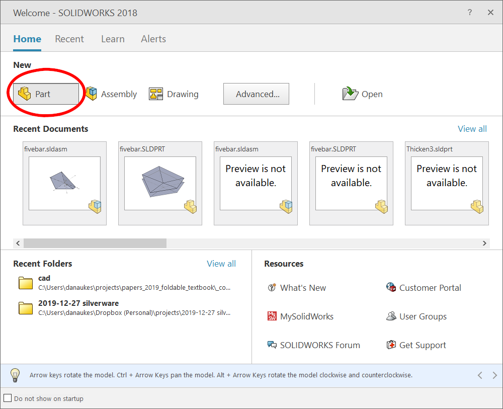
Create a new part
Select the Top Plane
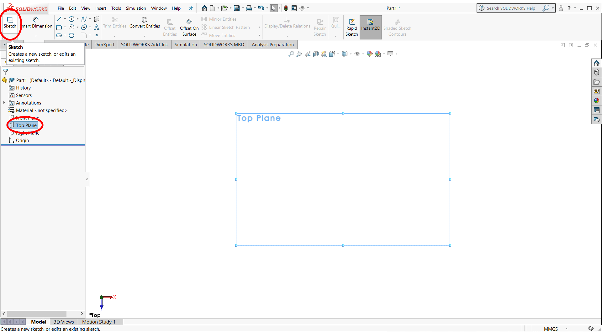
Create a new Sketch
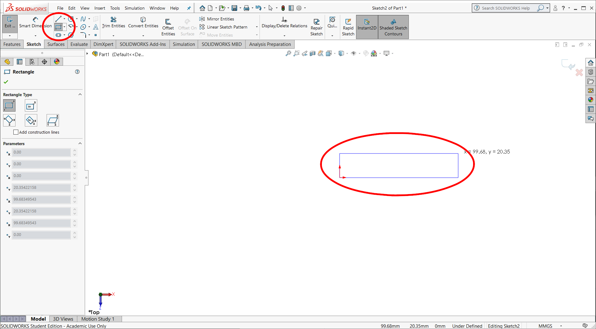
Select the rectangle tool
Draw a rectangle (hint: click on the origin to constrain the rectangle to that point)
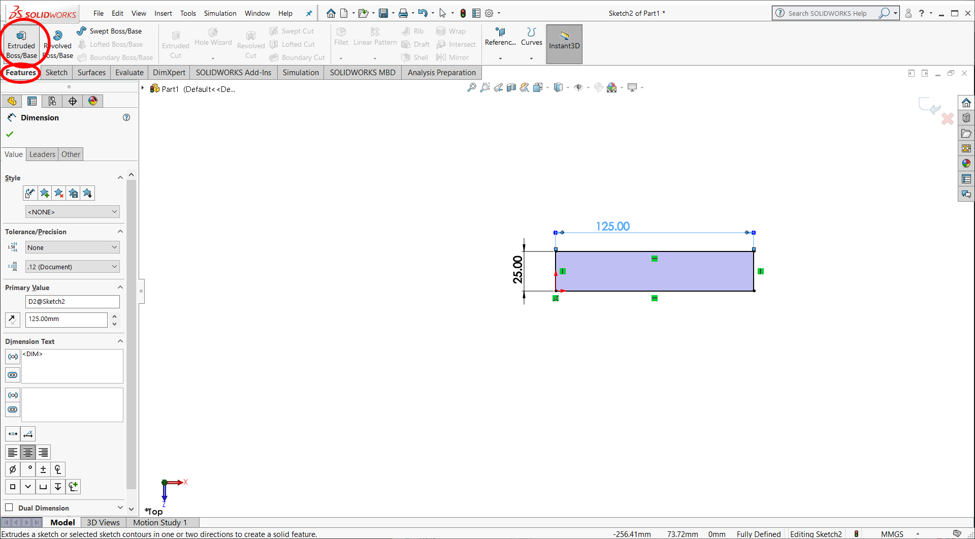
Select the dimensioning tool
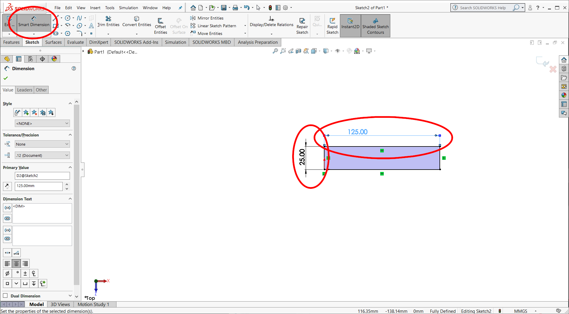
Click on the top edge of the rectangle. A dimension will appear. Enter the desired dimension
Repeat for the side of the rectangle
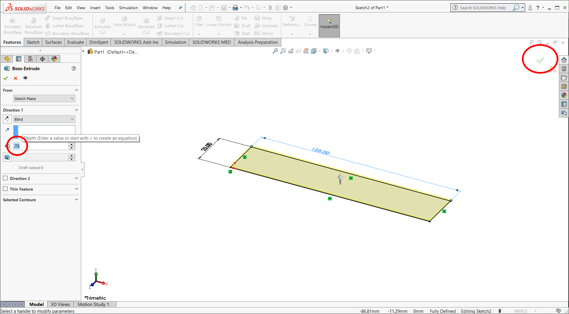
Select the features tab and then select extruded boss/base
Enter the thickness of your laminate
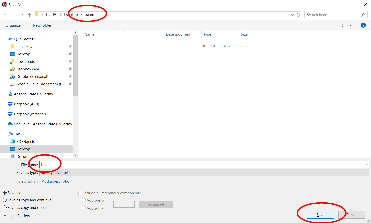
Save your part into a new folder
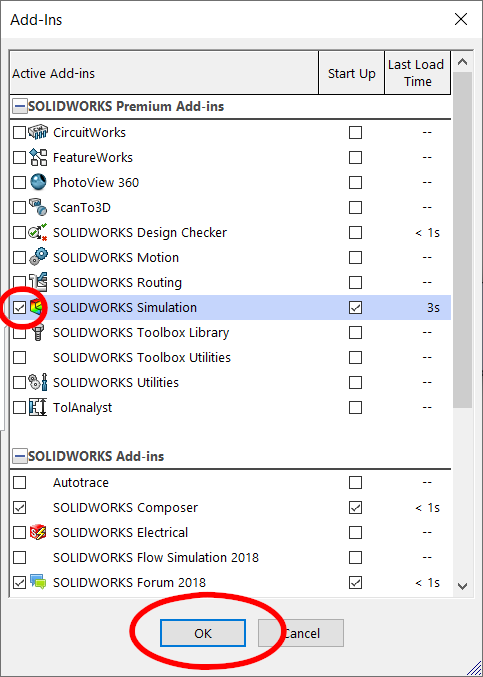
Turn on the Solidworks Simulaton Add in. Go to tools–>add ins
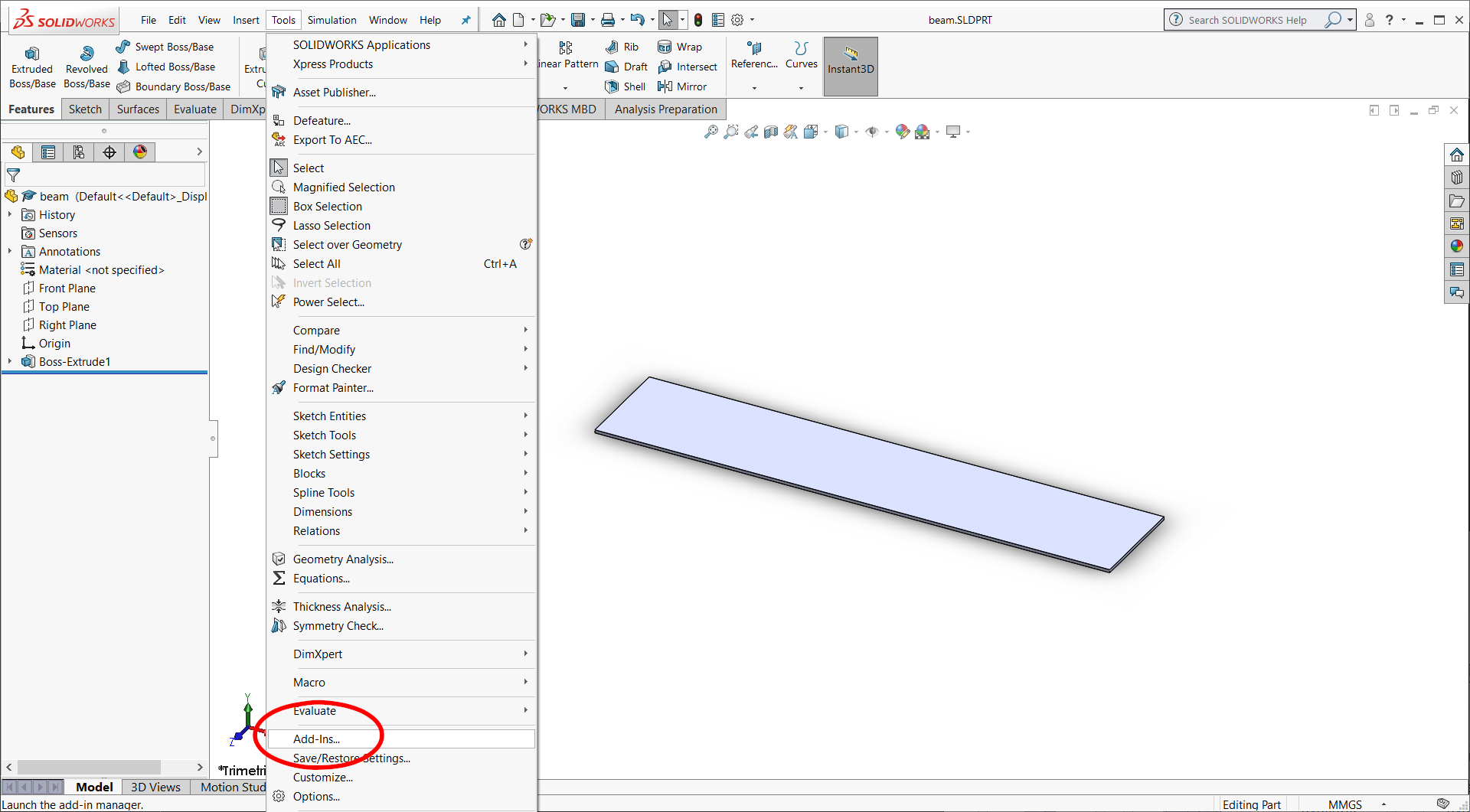
Click on the check box to the left of the “solidworks simulation item”
Now select the Simulation tab.
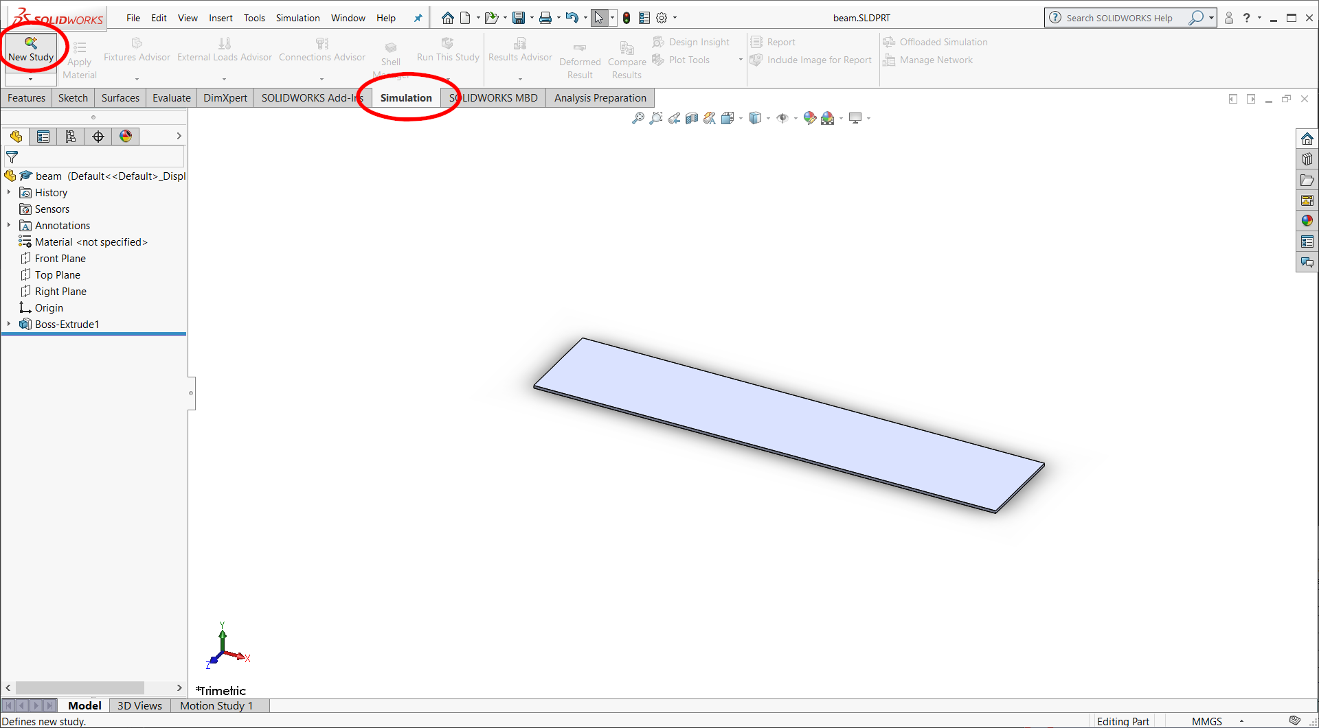
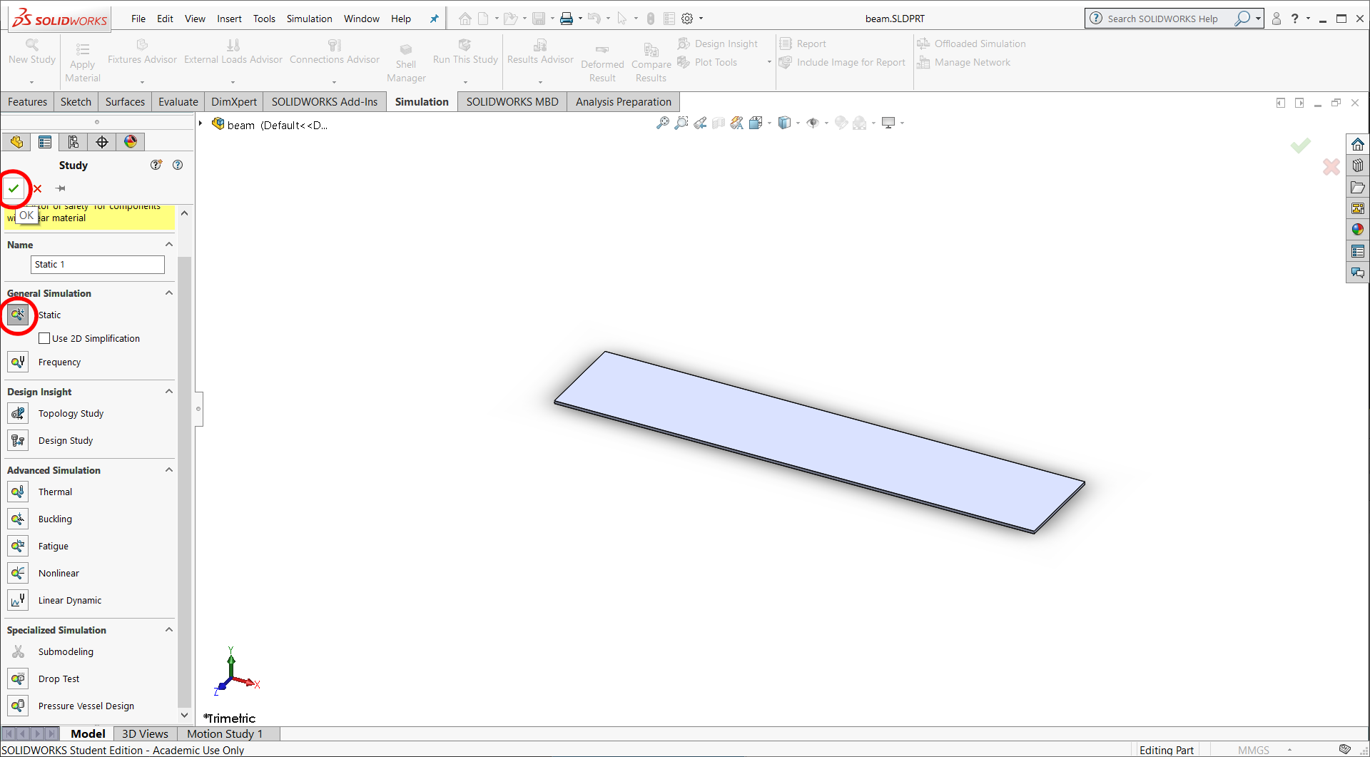
Create a new study
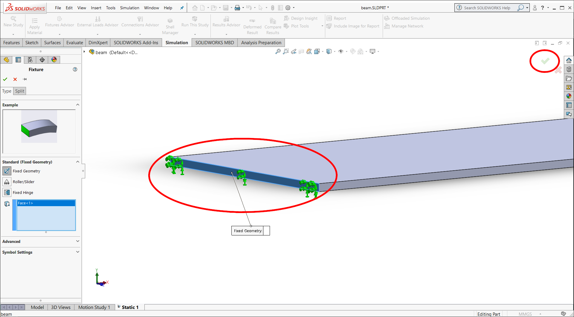
Next, define your fixtures. Go to the menu on the left and select fixtures–>Fixed Geometry…
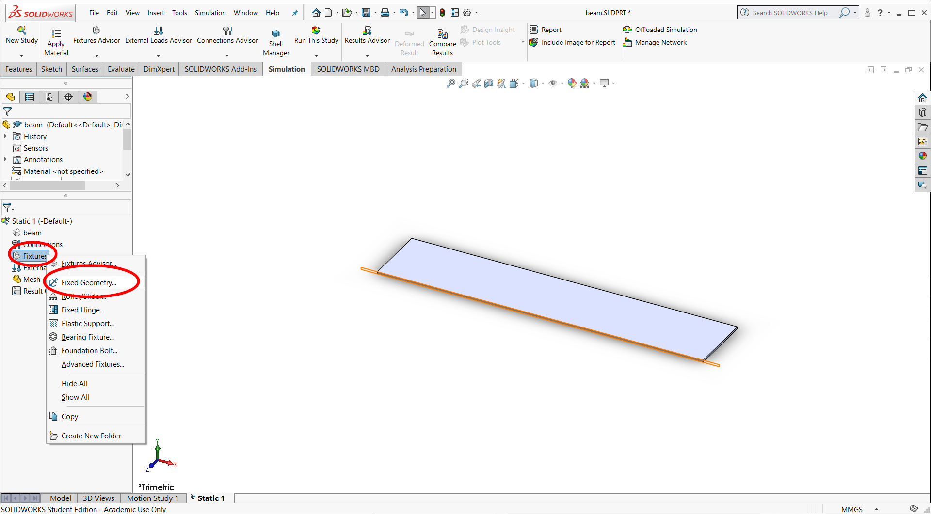
Define the fixed end of the cantilever beam by rotating the part and selecting the left cross-sectional face of the beam.
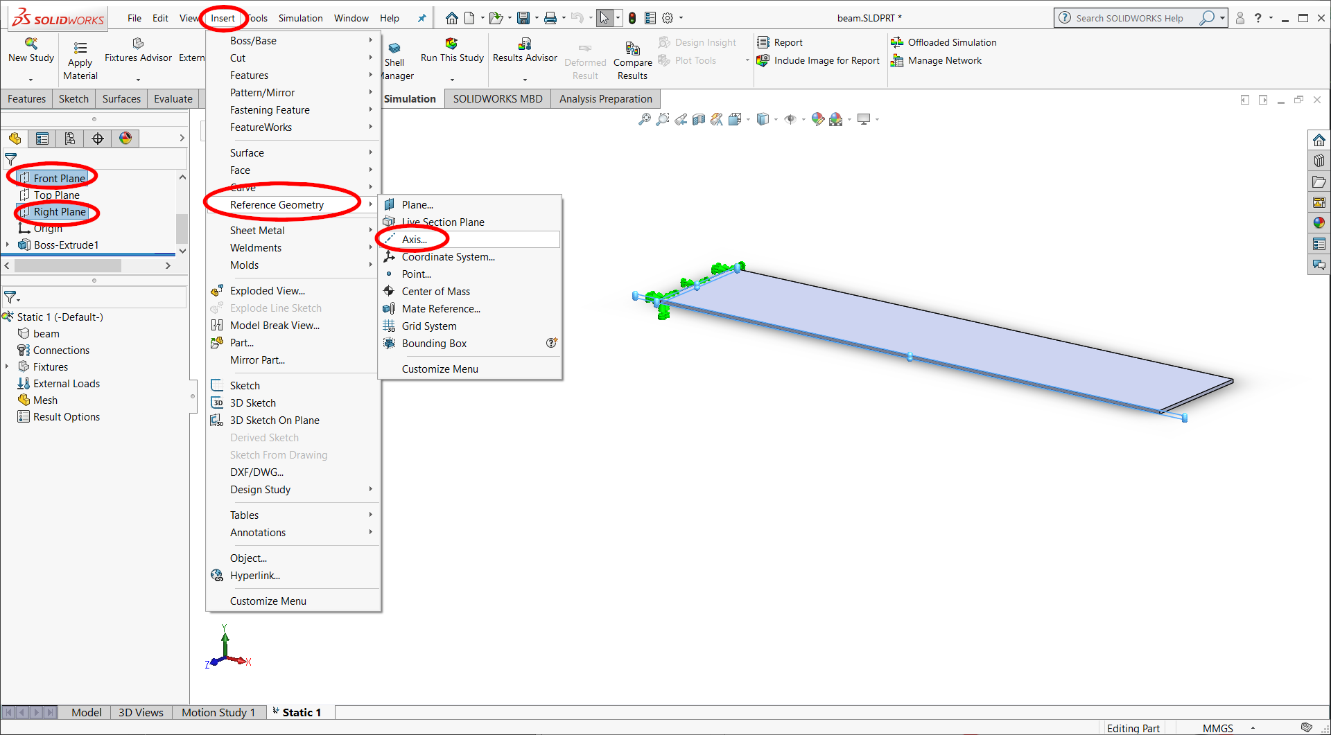
Define an axis along which you will align a force. Select The Front plane and the top plane, then select insert–>reference geometry–>axis from the top menu
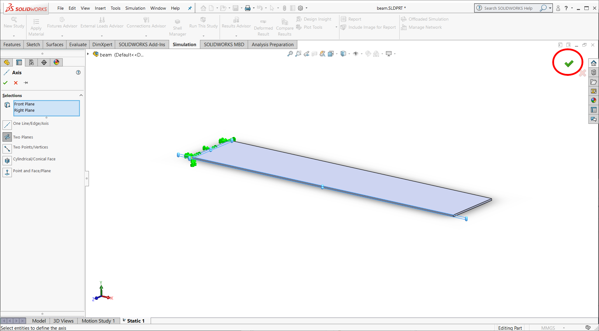
The two-planes method should be automatically selected for you. Select the green check mark to accept the new axis
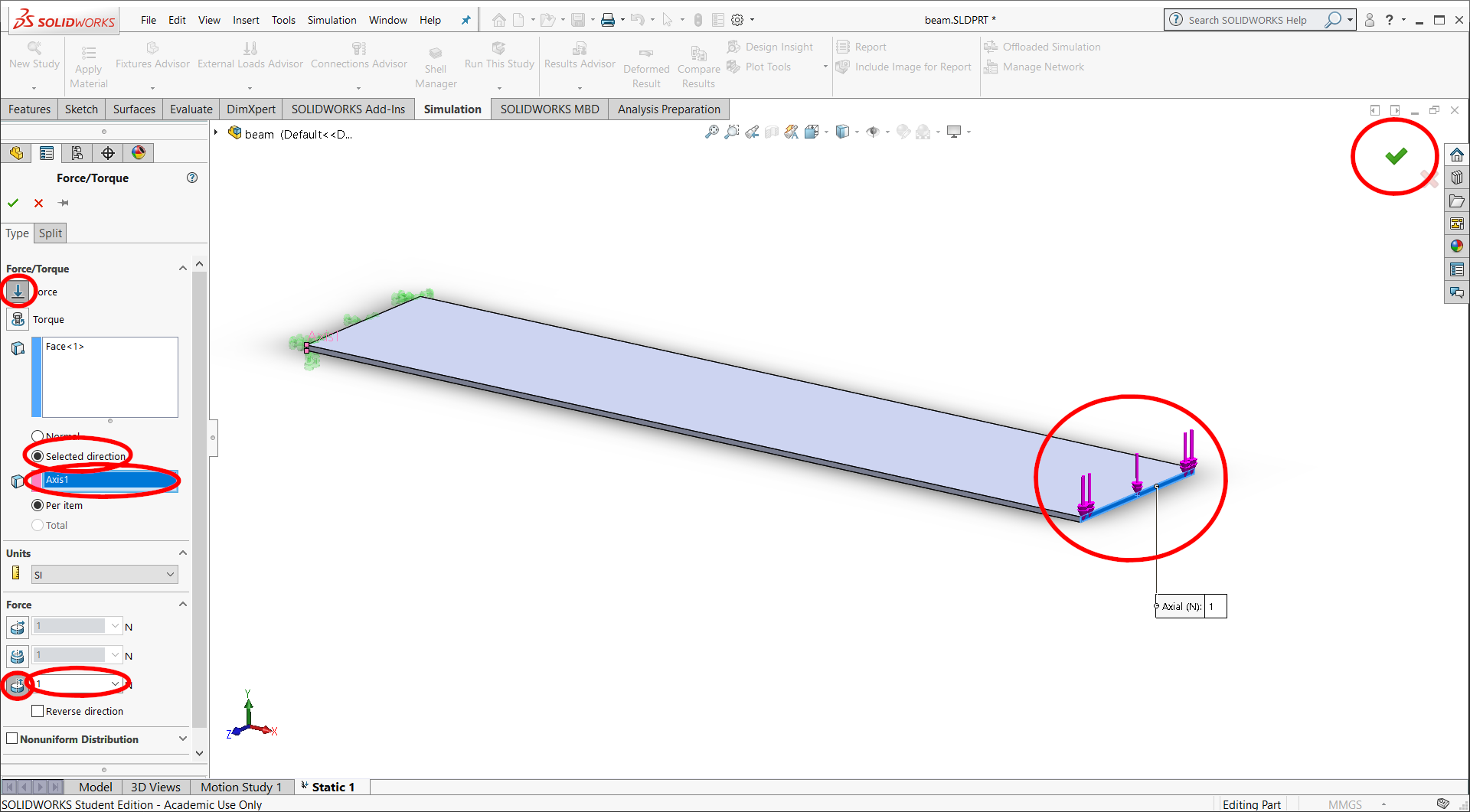
Define your forces. In the left menu select External forces/torques–>force…
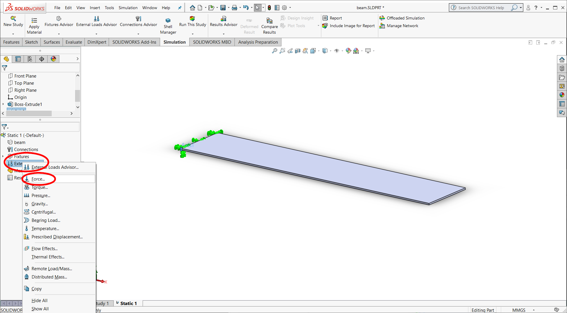
Select the right cross-sectional face of the beam, then ensure the force option is selected on the left. Check the “sekected direction option”, and the new axis you just created (axis 1). Then select the axial load option and define the magnitued of the force.
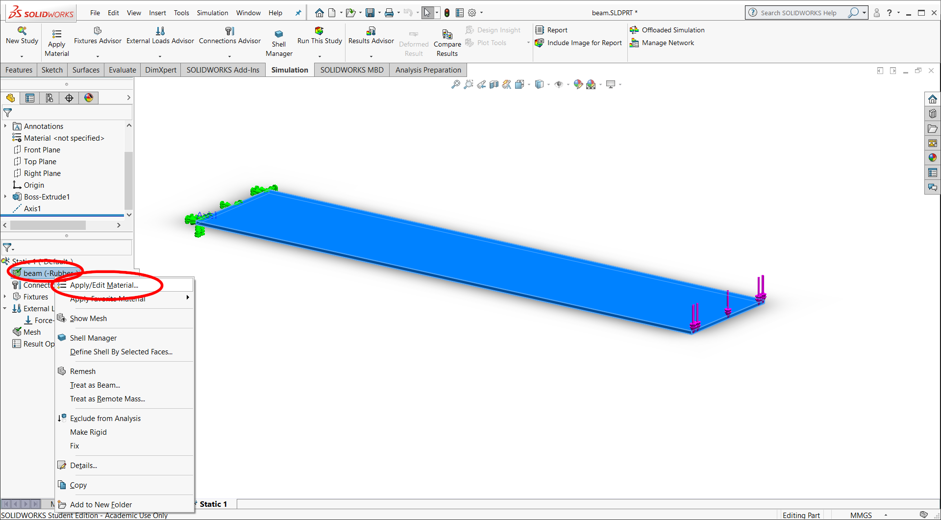
Next, define your material. You can select from a list of favorite materials, or go into the material selector to create a custom material.

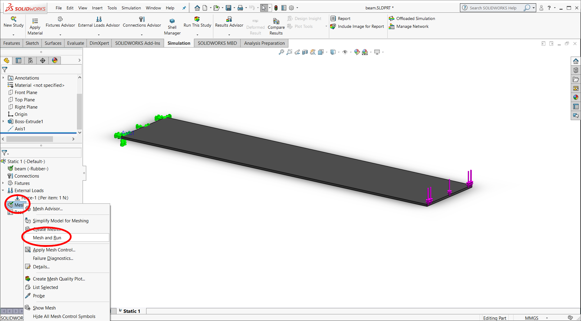
In the left menu, select mesh–>mesh and run to run your simulation
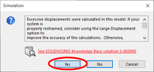
If you get a message that the solver failed, with an option to restart, select “yes”
If you get a message to turn on large displacement solving, select yes.
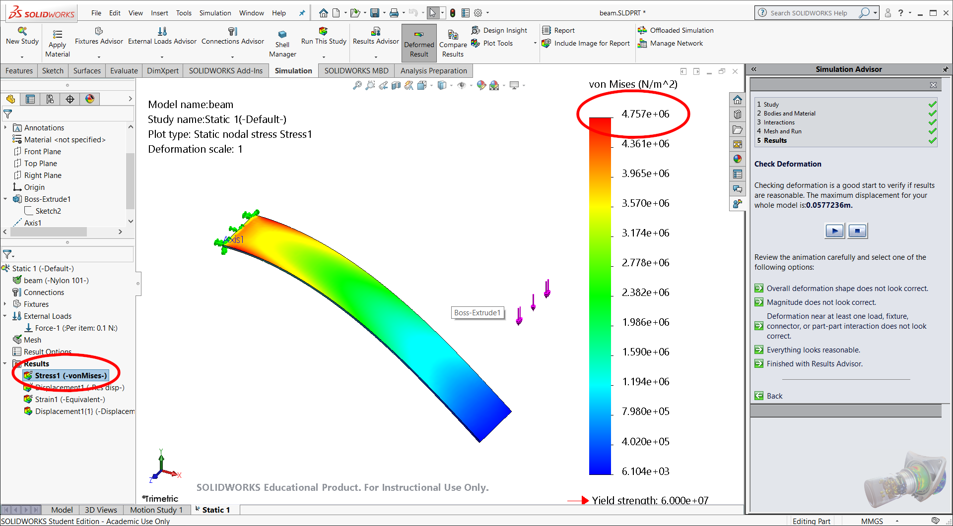
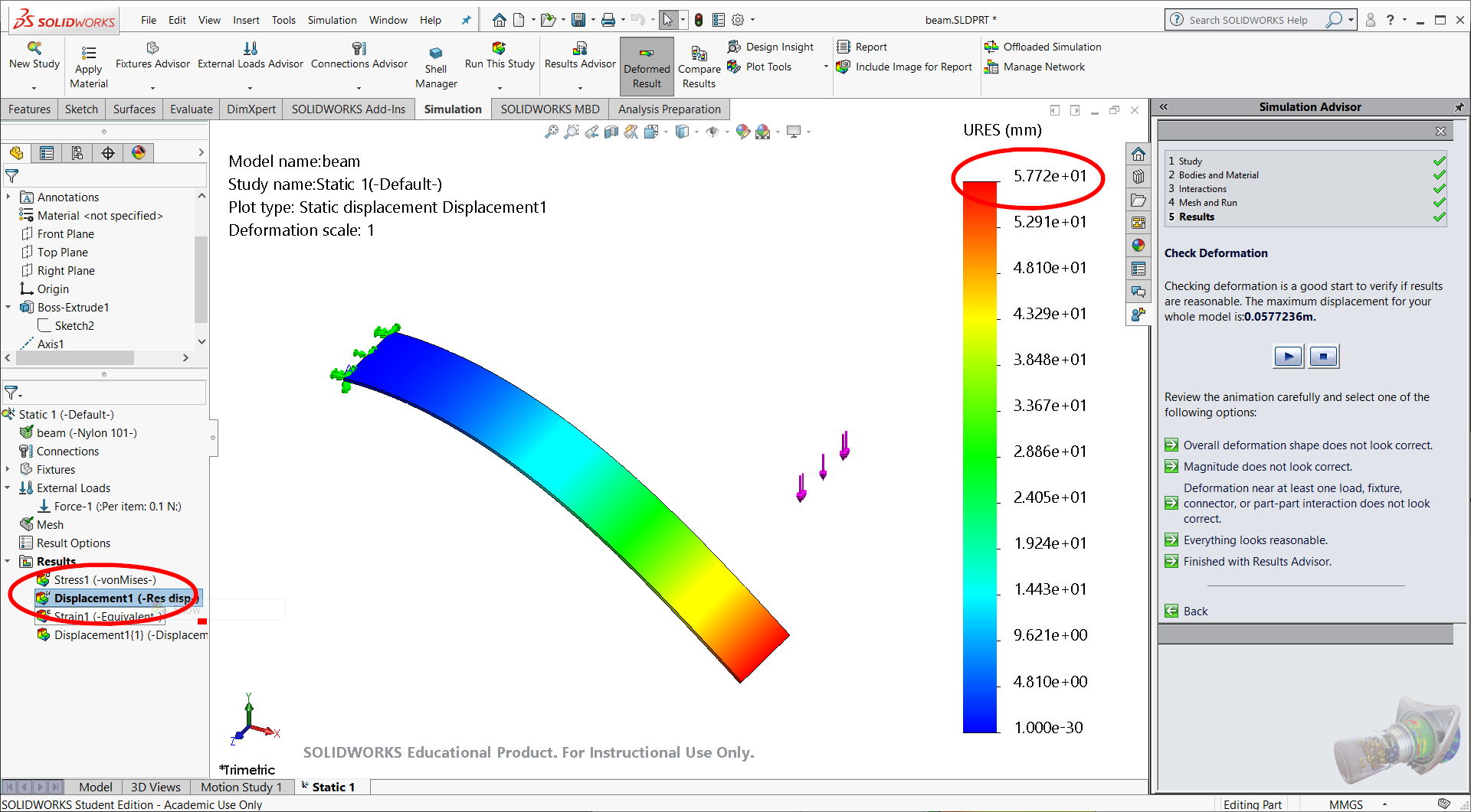
If it succeeds, you may now view the results of the solver
Notes
Common sources of failure include:
- Too high of a force or too soft of a material for the given dimensions. Try selecting a stiffer material